Introduction
Madrid has 5 skyscrapers, and all of them are located in the northeast part of the city, the so-called financial district. The name of this area is Four Towers Business Area, being the former Real Madrid Sports City. The construction of the first 4 towers started in 2004 and they were inaugurated between the end of 2008 and the beginning of 2009.
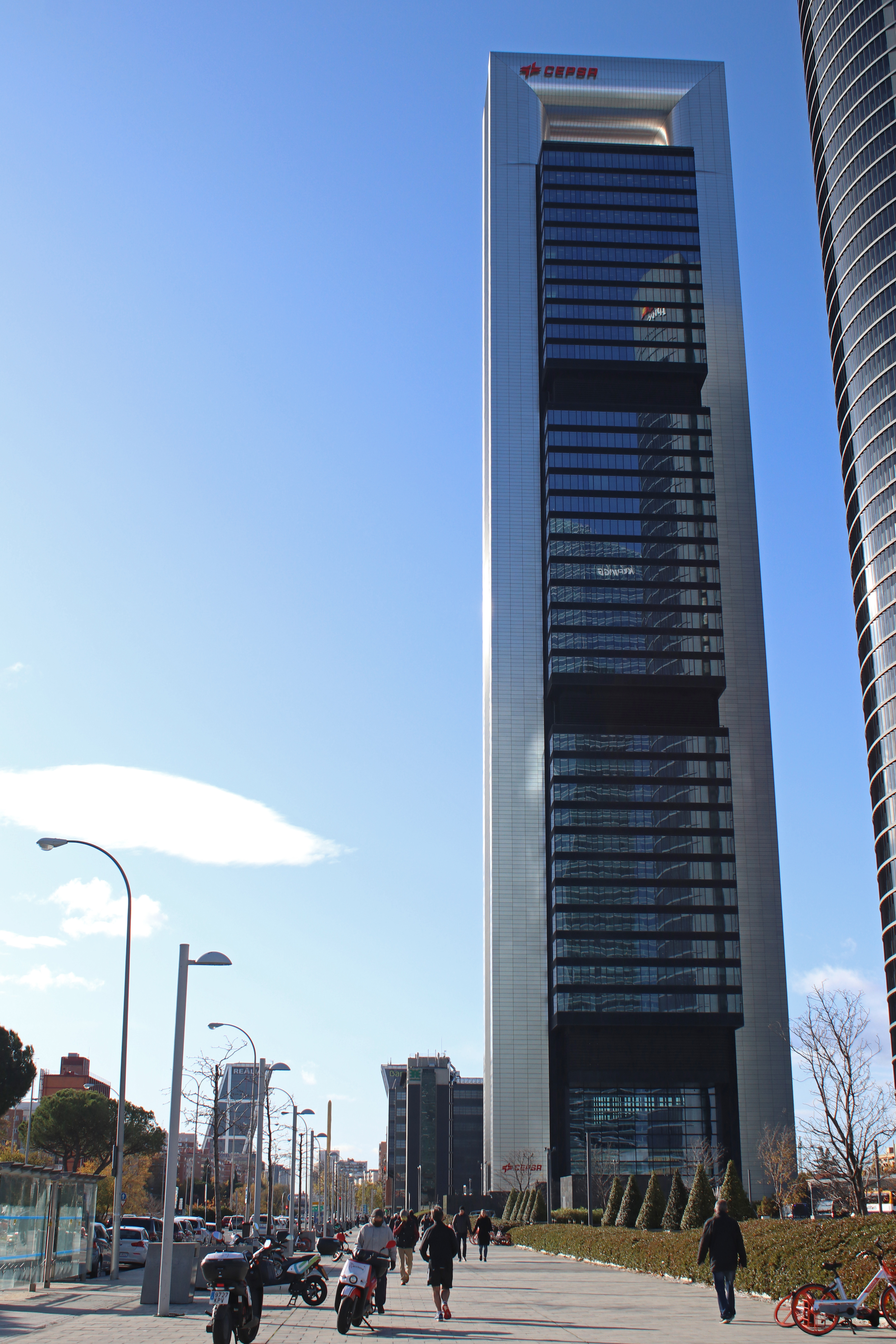
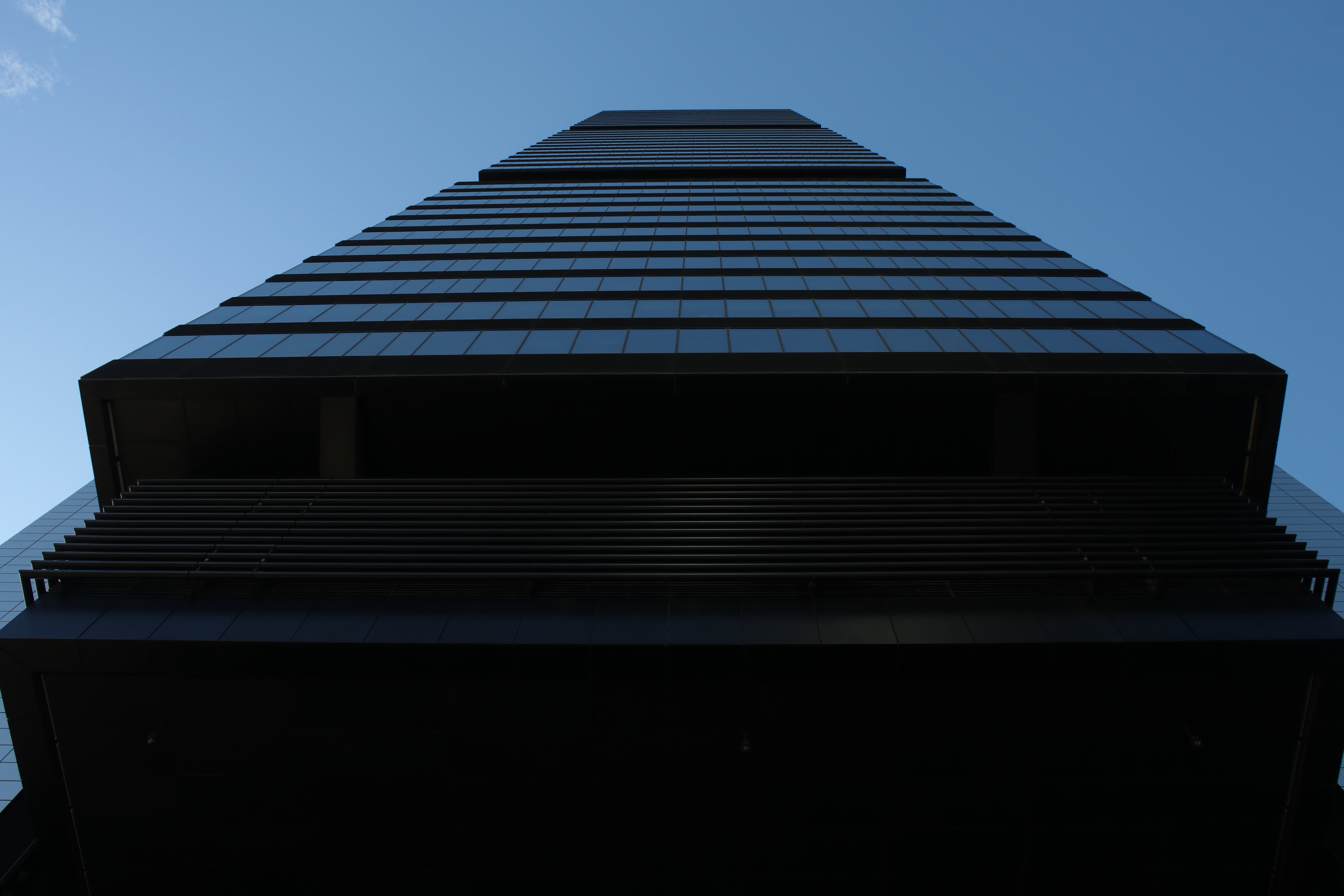
Cepsa Tower (firstly called Caja Madrid Tower) is the southernmost building. It is 248 m tall and the second highest Spanish skyscraper. Foster and Partners was the firm in charge of the architectural design, whilst the structural design was carried out by Halvorson and Partners (acquired by WSP in 2015).
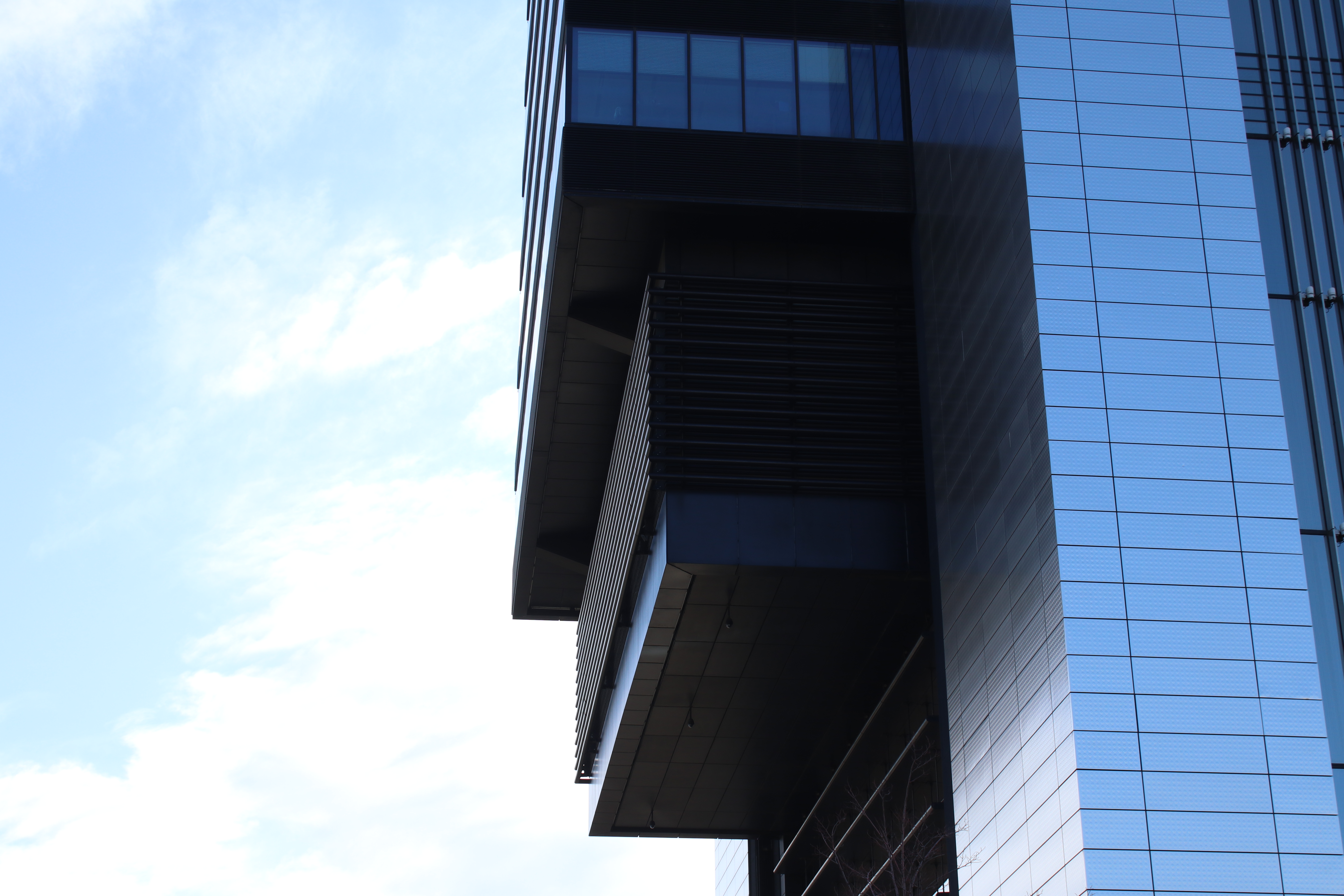
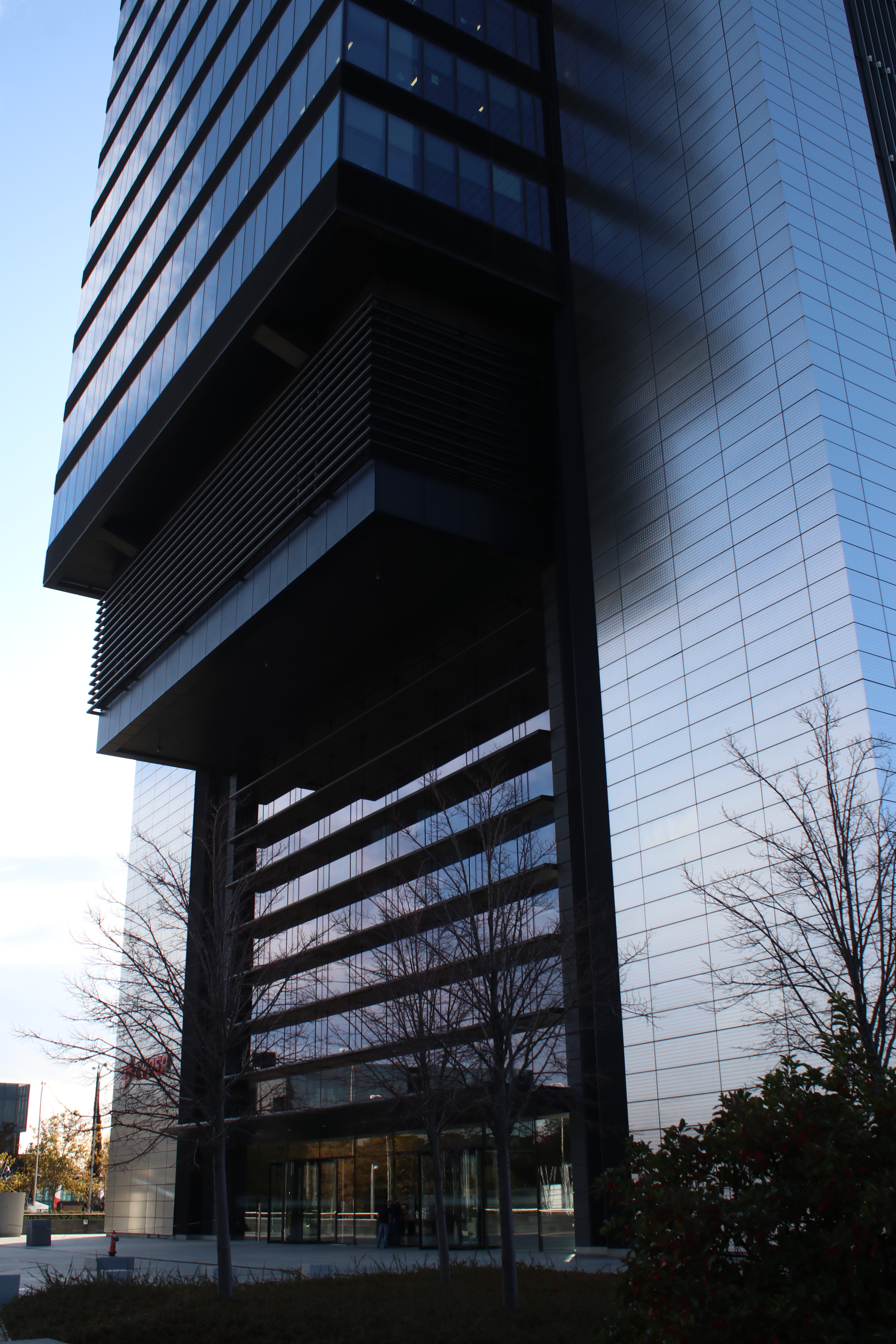
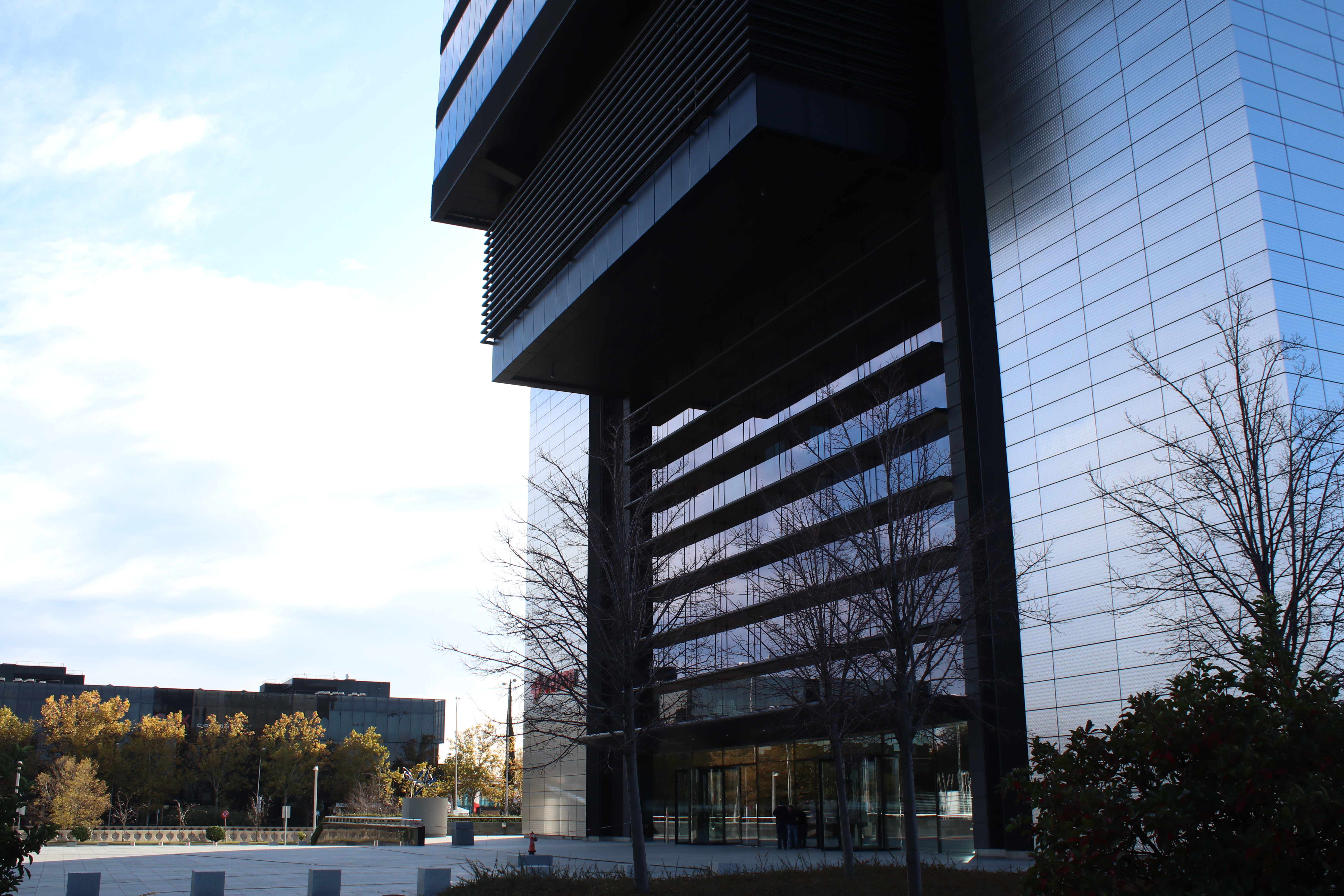
The main idea was to build a skyscraper with a big open entrance, creating a space in communication with the outside. Because of that, there are no columns on the ground floor, and so the loads coming from the building rely only on the two recognizable cores.
The tower occupies about one third of the surface of the plot, so the other area becomes urban space. Under the esplanade, occupying the entire surface of the plot, there are five parking floors.
Main challenge: wind loads
The design of the structure of a skyscraper has to deal with the lateral loads coming from the wind action and/or seismic action. Madrid is not located in a seismic area, so wind loads will condition the design of the structure.
In order to determine those forces, wind tunnel tests were carried out. Wind tunnels are big hollow tubes with powerful fans at one end that create a flow of air. Inside the tunnel, a scale model of the structure (building, bridge, etc.) is placed. With this, the interaction between the wind and the structure can be analyzed. There are many factors to take into account. For example! A skyscraper in the financial district of New York, with many other high buildings around, doesn´t behave as Cepsa Tower in Madrid.
Where is the wind tunnel used for this building? In Canada! The analyses was carried out in the Boundary Layer Wind Tunnel Laboratory in the University Of Western Ontario, Canada. Professor Alan G. Davenport was in charge.
They not only defined the wind loads to be applied for designing the tower, but also the maximum accelerations in the building when wind blows. If these accelerations reach a certain threshold, building users can feel insecure (they feel the building is moving) or even get dizzy. In an office building, maximum acceleration allowed is 2% of the gravity’s. This dynamic control based in accelerations is used for high buildings, whilst in common buildings is frequently used a control based in deformations under static loads.
Structural design
The structural design of buildings this size has to deal with, as explained before, not only vertical loads such as the structure’s and interior elements’ weight and the live load coming from the users but also the lateral loads, which is only the wind in this case. In a small building, the lateral load resisting system would not be so outstanding.
Looking at this impressive tower, we quickly see two recognizable elements:
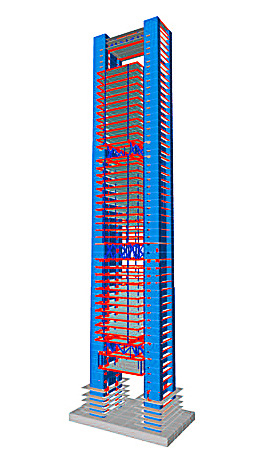
ETABS structural calculation model
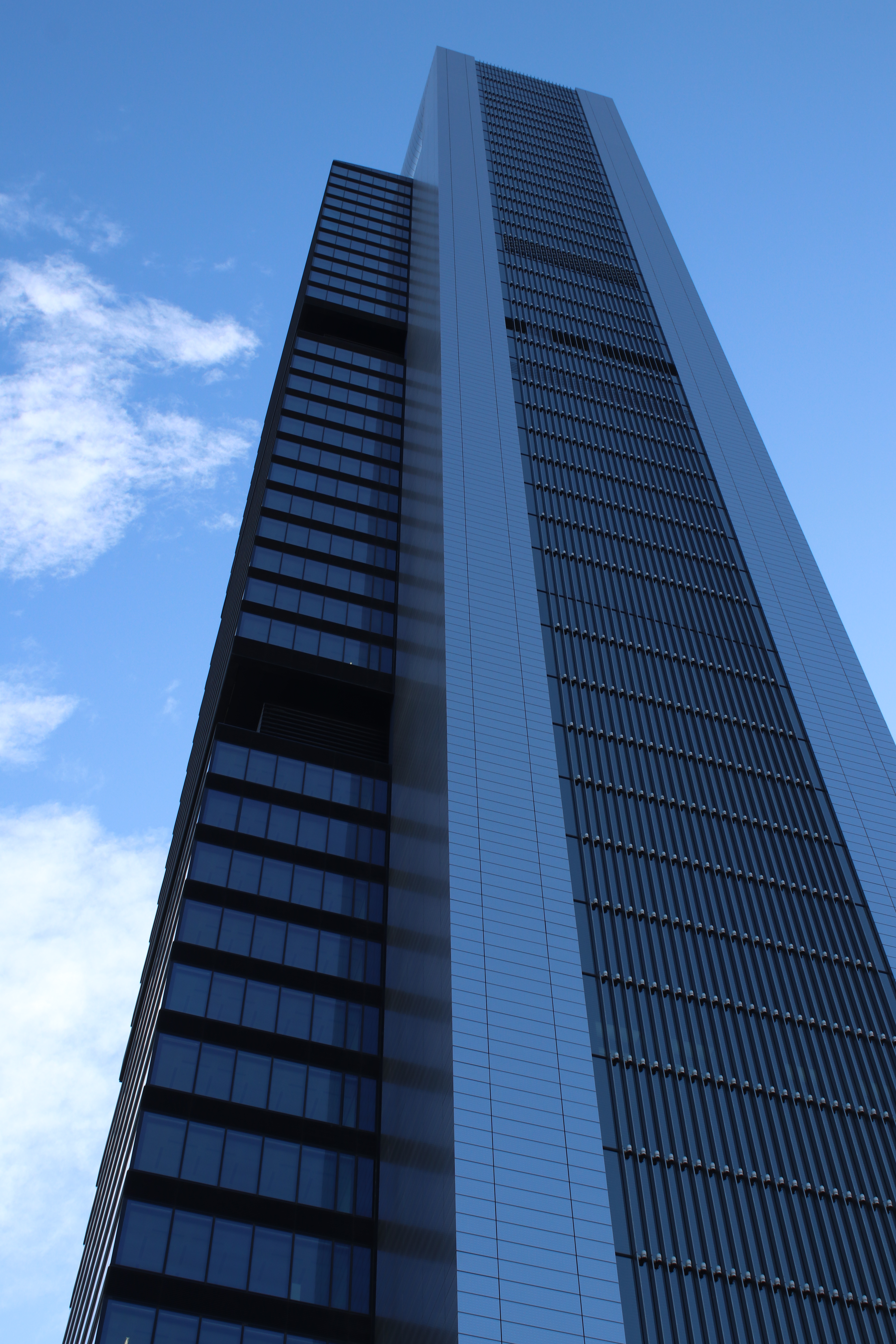
- The two lateral cores, which extend over the entire height of the building, joined at the top by a horizontal element.
- The building floors division into three groups of about 11-12 floors each. We can consider the large entrance hall as a different part.
The structural concept for resisting the vertical loads is based on transmitting them to the cores as they descend through the building. This system avoids doing it all at once, right before reaching the lobby.
Let’s analyze the load path.
The typical office floor in this building is 32 m east-west (distance between cores) and 42 m north-south (with 9.5 m overhangs on both sides). A group of steel beams separated 3 m between axis form all these floors, and they support a concrete decking slab 15 cm thick. This type of construction consists of a profiled or “corrugated” steel sheet, which acts as permanent shuttering for a reinforced concrete slab poured on top so that the steel sheeting “collaborates” with the concrete slab.
Then, 8 columns support each floor: 4 are placed in the perimeter (on the north and south facades), and 4 are interior. The loads go down these columns until they reach the bottom of the corresponding block of floors. There, loads are transferred from the columns to 2 trusses, called secondary, and placed in a north-south direction. These bear on two other trusses called primary, which are located in an east-west direction.
And this is not all! These primary trusses link one core to the other. The connection is made through columns embedded in the concrete of the cores. Loads coming from the above block are transferred to the cores, go down through them to the foundation, and finally to the ground.
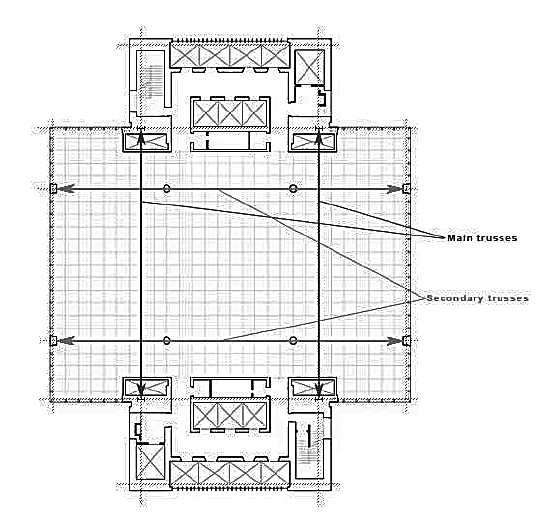
Typical floor plan
The trusses are two floors high, and technical floors are located at that level. In addition to supporting the vertical loads, they collaborate with the cores in resisting the E-W wind loads. In the N-S direction, each core withstands alone its corresponding wind loads. To make this collaboration possible, engineers designed diaphragms at the level of the upper and lower chords of each truss. They are post-tensioned slabs 1.9 m thick, allowing the loads to be transmitted. The lower chord of the main trusses is also post-tensioned, to guarantee the redundancy of the system.
At the top of the building, instead of using trusses to link the cores, two “wall” beams are arranged constructed. This link is, in this case, a simply supported element that does not collaborate like the other links in resisting the lateral loads because it was not needed, and it was easier to be constructed this way.
Foundation
The foundation of the tower consists of a post-tensioned concrete slab, resting on top of a type of clay in Madrid called “toscos”. The allowable stress is about 7kp/cm2. There are not two slabs, one for each core, in order to avoid differential settlements between them. The foundation slab is 43x72x5 m, and the maximum settlement is 5 cm.
Other structural data
- A structural detail at columns mid-height between floors, allow some vertical movements to accommodate creep and shrinkage deformations of the cores and the other supports.
- Also, every block of floors can move independently, at mechanical floors level.
- After 9/11 terrorist attacks, new redundancy requirements were incorporated in the design of structures. For this building, trusses and interior columns are designed so that if one of the levels collapses, the contiguous level can hold its weight plus its own.
Photos
Photos by Behind A Great Project
Other images
-

- Typical floor plan
-
- ETABS structural calculation model
-
- Construction


