Introduction
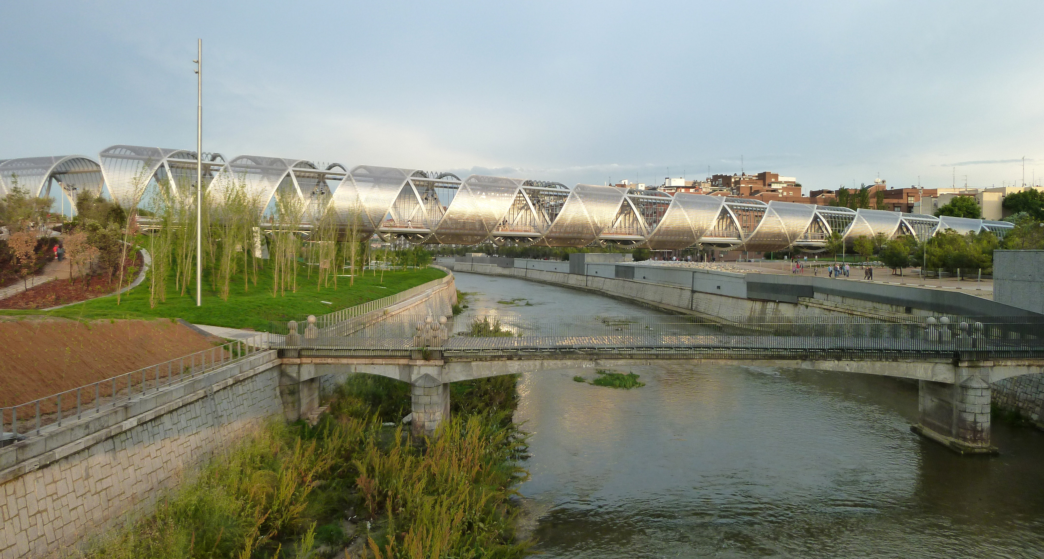
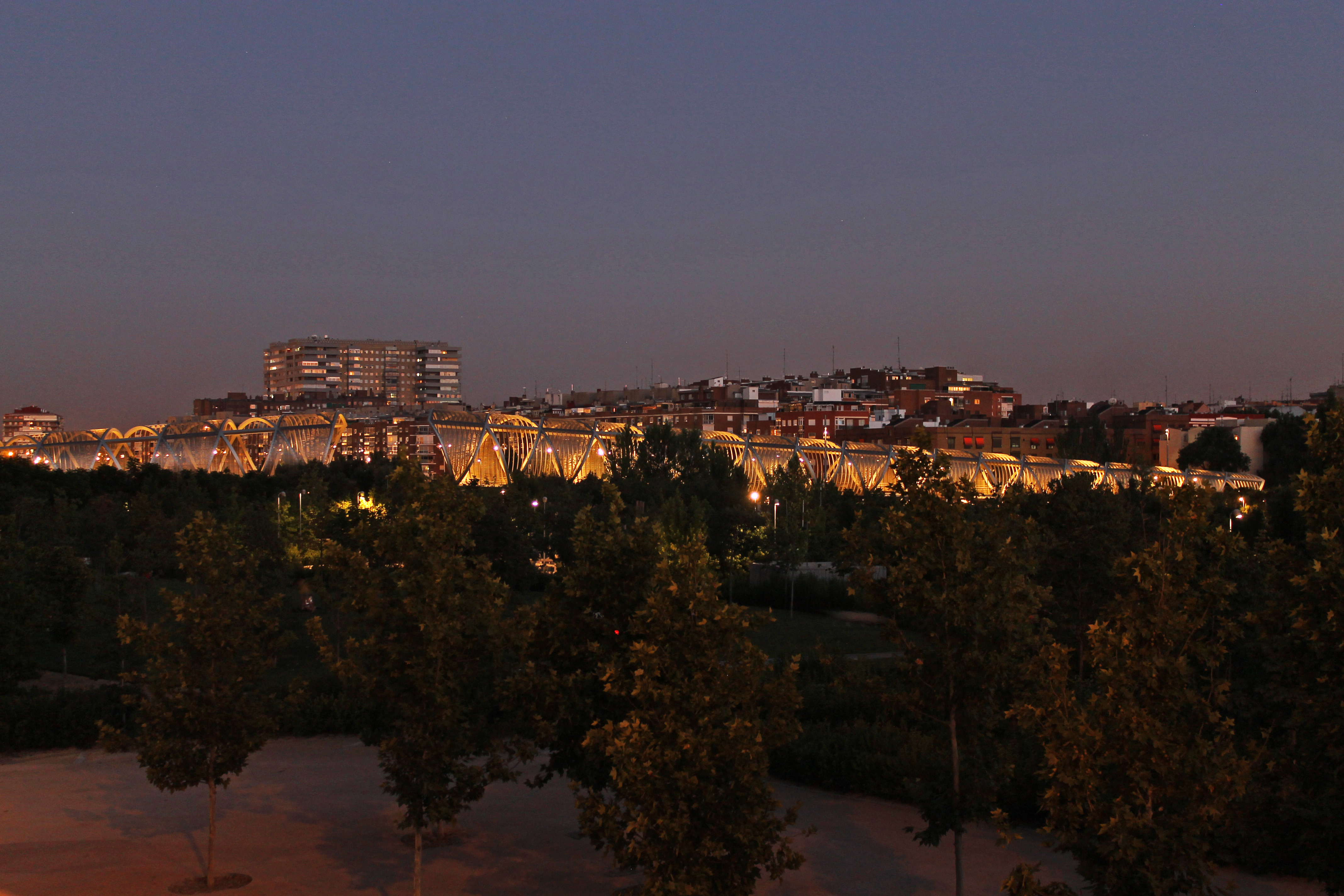
Arganzuela footbridge is located at Madrid Río. Madrid Río is a park in the city of Madrid, Spain, built after “burying” the M30 multilane highway, which resulted in the world’s longest urban tunnel, and a great leisure area on top. This park, at the Manzanares Riverbank, serves as a connection for Arganzuela and Carabanchel districts, between Antonio López street and Paseo de Yeserías.
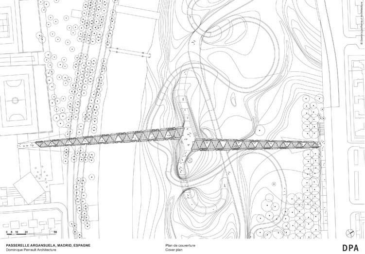
The footbridge consists of two single-span bodies, whose axes are not aligned, that meet at an artificial hill that provides access to the Arganzuela Park. They have lanes for pedestrians and cyclists. The south footbridge is 150 m long with a main span of 115 m over the Manzanares River, whilst the north footbridge is 128 m long with a main span of 96 m over the Arganzuela Park. The two bridges are inscribed in a tronco-conical surface, and their transverse circular cross section is linearly variable in diameter, from 6 m in the smaller ends up to 12 m at the greater ends.
Structural design
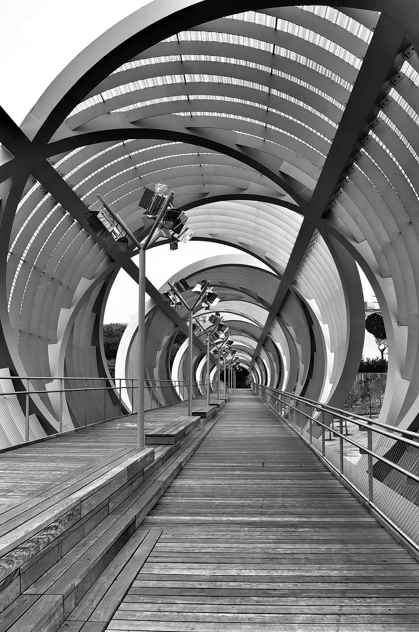
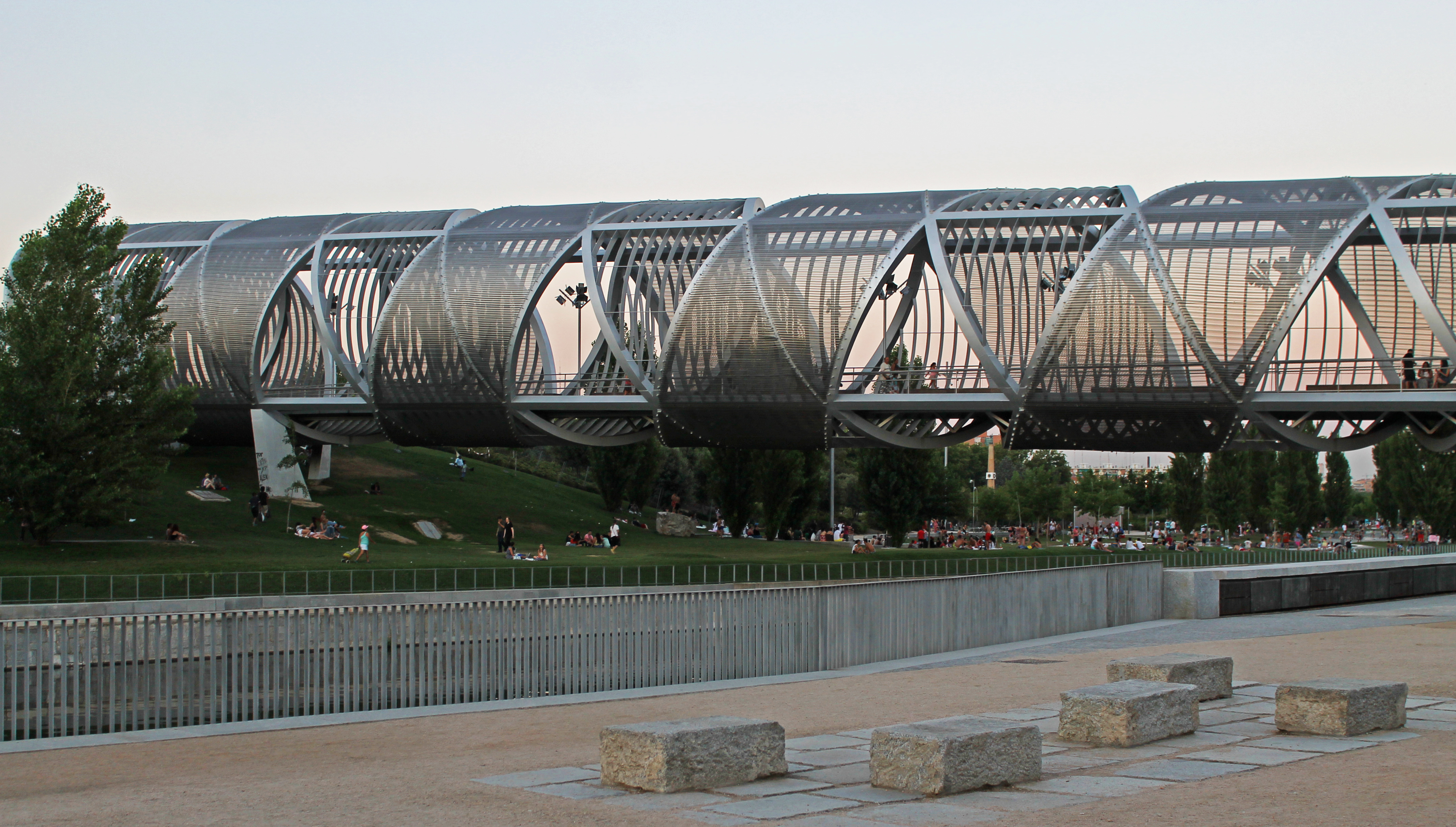
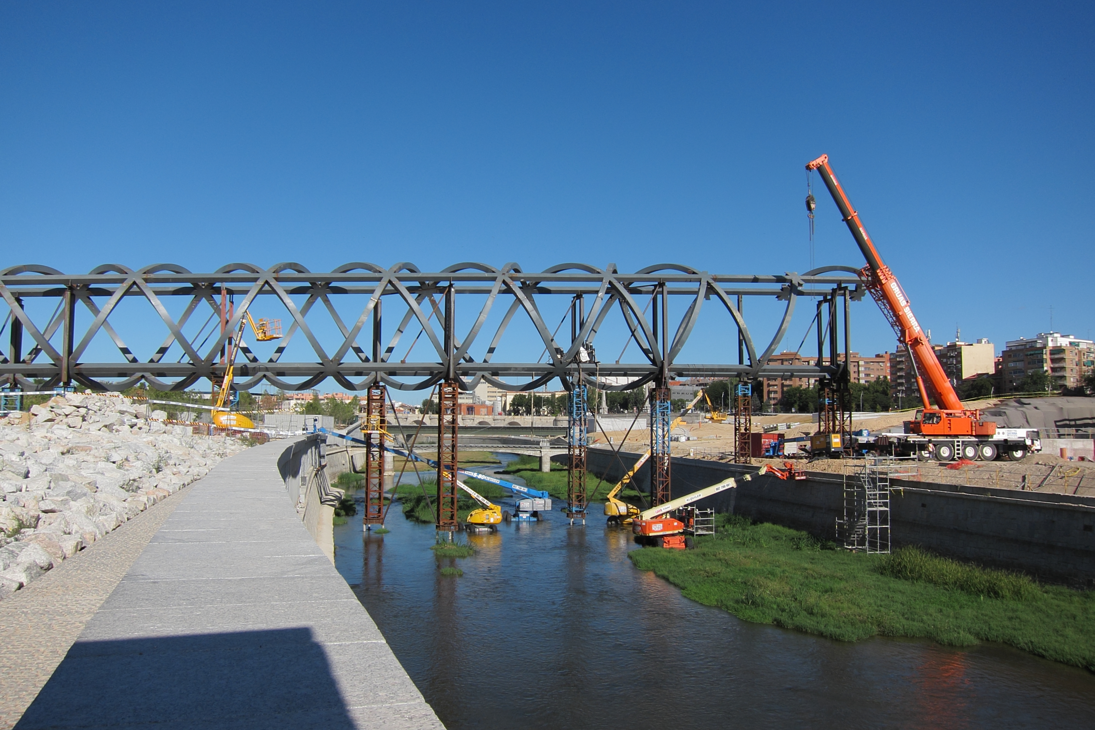
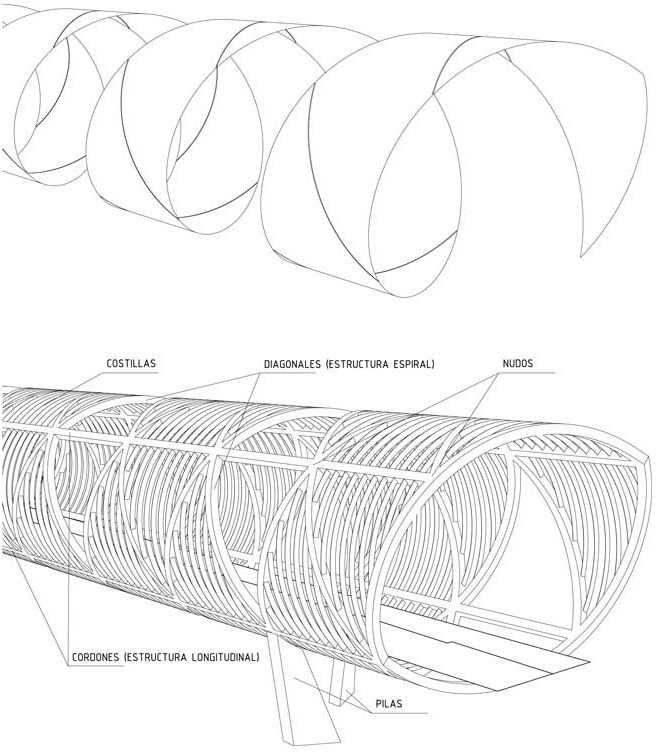
The structure is a spatial truss, but not common because the diagonals are curved. There are many elements in these trusses, but the structural ones are the curved diagonals and the four straight longitudinal cords, set 90º apart and that have a pseudo-square cross section of 450×450 mm. The nonstructural elements are the steel ribs that support a permeable skin made out of a metallic mesh which covers two-thirds of the surface giving shade to the pedestrians.
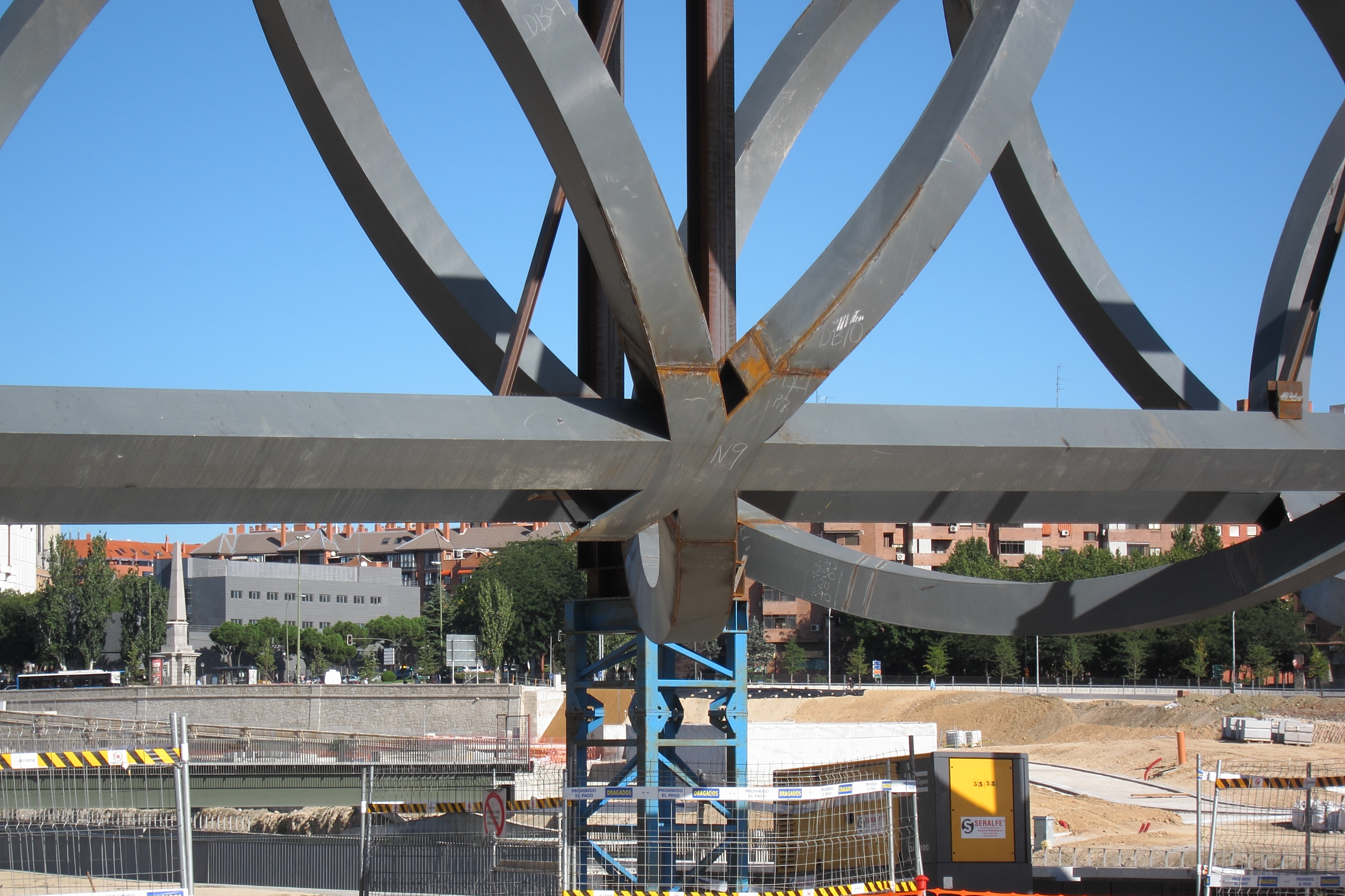
The diagonals run along four helixes that may be grouped into two families of contrary directions. This way, six bars meet at each node of the truss (a longitudinal chord and two helixes), existing 139 nodes in total. The diagonals are also pseudo-square sections, and as the chords, the outer and inner faces are curved, contained in two conical surfaces, while the other two faces are set perpendicular.
The configuration determines two pseudo-Warren trusses with out-of-plane curved diagonals, connected through two other sets of pseudo-Warren out-of-plane diagonals on the top and bottom. The curving of the diagonals introduces undesirable bending stresses in them, and so losing part of the truss efficiency. This would not happen in a conventional truss with straight elements. This is critical at the diagonals close to the piers, where big shortening and elongation produce significant shear deformations.
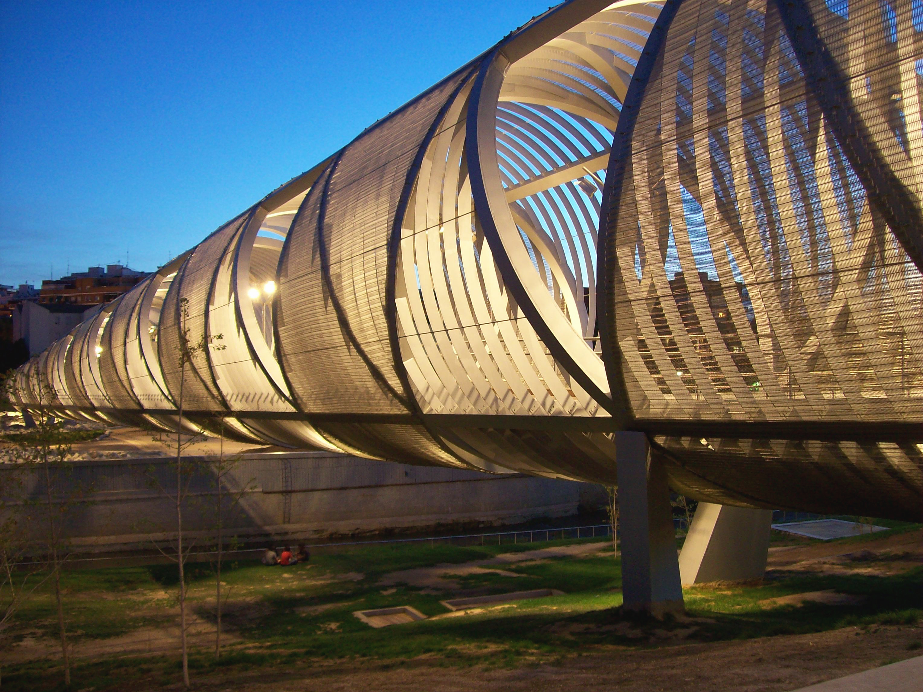
There is one pair of inclined prefabricated piers at each end of each bridge, which more or less follow the direction of the main diagonals. The “double inclination” of the piers implies great bending stresses. In order to reduce them, a staged construction was devised.
In the first phase, the bases of the piers were pinned to allow rotation when the structure was unpropped, under its self-weight and dead loads, and so behaving as simply supported beams. In a second phase, after this rotation took place, the bases were restrained to act as a rigid connection from then on. Thus, under service loads, the base of the piers is fully restrained.
The upper end of the piers is fully, continuously welded against the main diagonal that transfers the vertical load from the main structure. The other bars that meet at the joint (chords and diagonals) have pinned (hinged) connections to remove secondary bending moments and high stresses that enter the piers through the strangled neck connection. These hinges have a very complex geometry due to the crooked inclination of the piers in relation to the main diagonals, and are fitted inside the small dimensions of the longitudinal cord.
Foundation is formed by piles and micropiles, and each pair of piers share a common pile cap. Three of the four pile caps are right on top or next to the underground motorways or sewers.
Other structural data
- There is a metallic structure in the inside of the bridges which holds the wood surface.
- In between the bridges there is an artificial hill supported by two metallic decks, separated in height. The lower deck spans between M-30 tunnels under it and the upper one supports the area where pedestrians and cyclists circulate. In between, the artificial hill is filled out of expanded polystyrene, and buried, in order to allow access to the park.
Video
(It allows automatic English subtitles)