Introduction
Cibeles Palace is a set of two buildings with white facades, located on one side of the Plaza de Cibeles in Madrid, Spain. These buildings were built between 1907 and 1919 on an area that was part of the Retiro Gardens. They were established as the headquarters of the Spanish Society of Post Office and Telegraph Service, and that’s why it was called “Palacio de Comunicaciones” (Communications Palace). It is one of the most representative examples of Spanish modernist architecture, designed by young Spanish architects Antonio Palacios and Joaquín Otamendi, who had a successful career after that.
Throughout the 20th century, different renovation processes were performed, but the Post office lost importance with the increasing years of the century. In 1993 it was declared a Site of Cultural Interest, with the category of Monument, and in 2003 the competition for the total renovation of the building was announced. Arquimatica, an architectural studio, presented the renovation project in 2005. At the end of 2007, it began to serve as the municipal offices of the Madrid City Council, changing its name to Cibeles Palace.
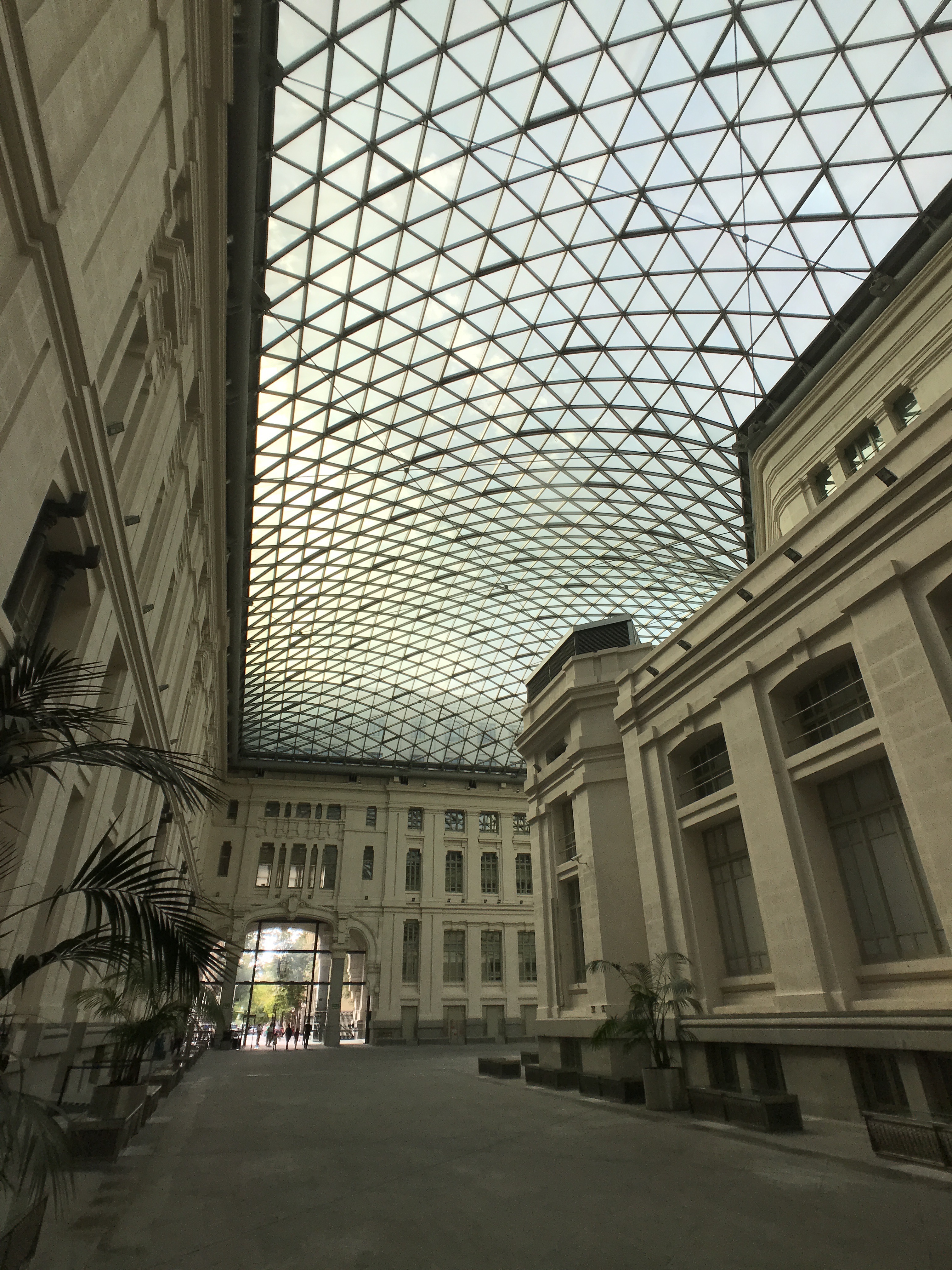
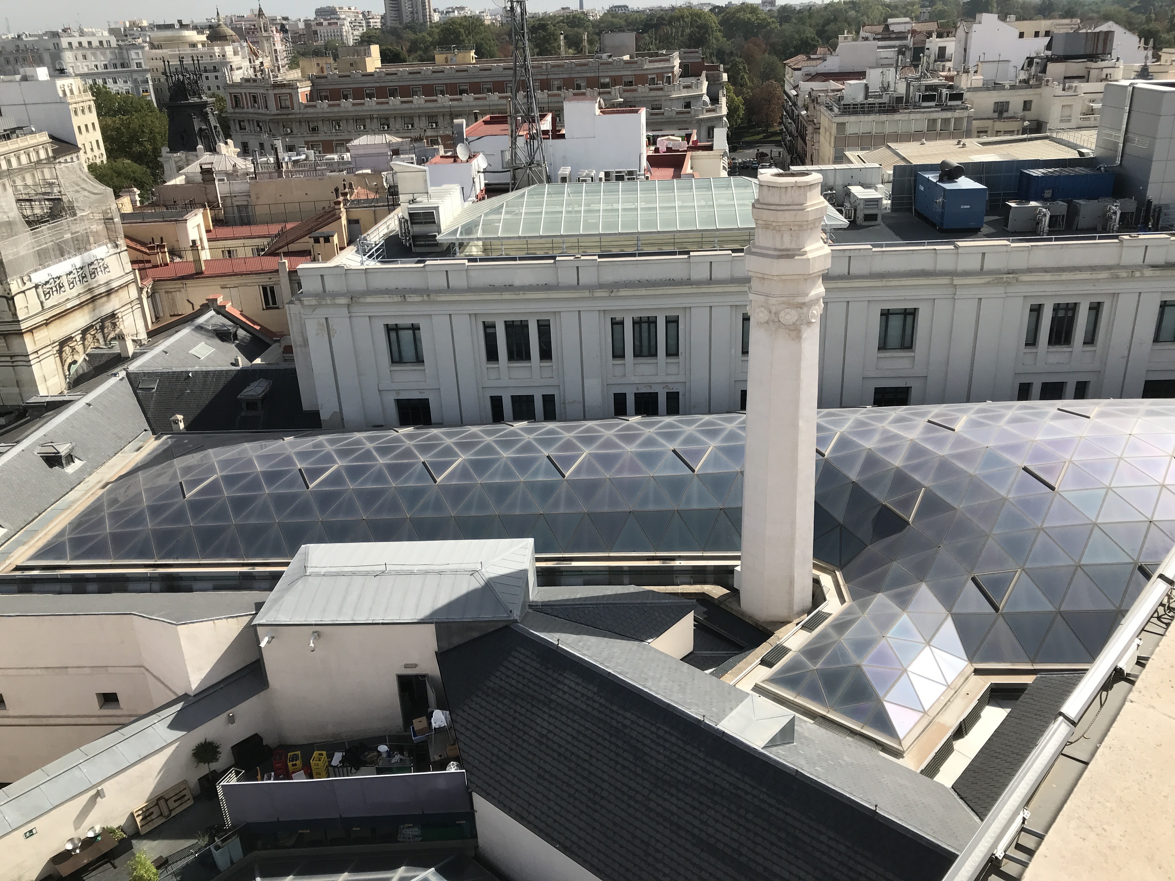
As part of the works that were carried out, the engineering company Schlaich Bergermann und Partner was invited by the architects to make the detailed design of a new glass roof, which would cover the Alarcón Passage. It is formed by a courtyard 130 m long, 15 m width, and the “Dock of Vans”, which has 600 m2. The passage separated the Direction building of the Management building and communicates the streets of Alcalá and Montalbán, next to which the widening called “dock of vans” sits (it was dedicated to mail transport cars). After the construction, this entire covered area is called the “Glass Gallery”.
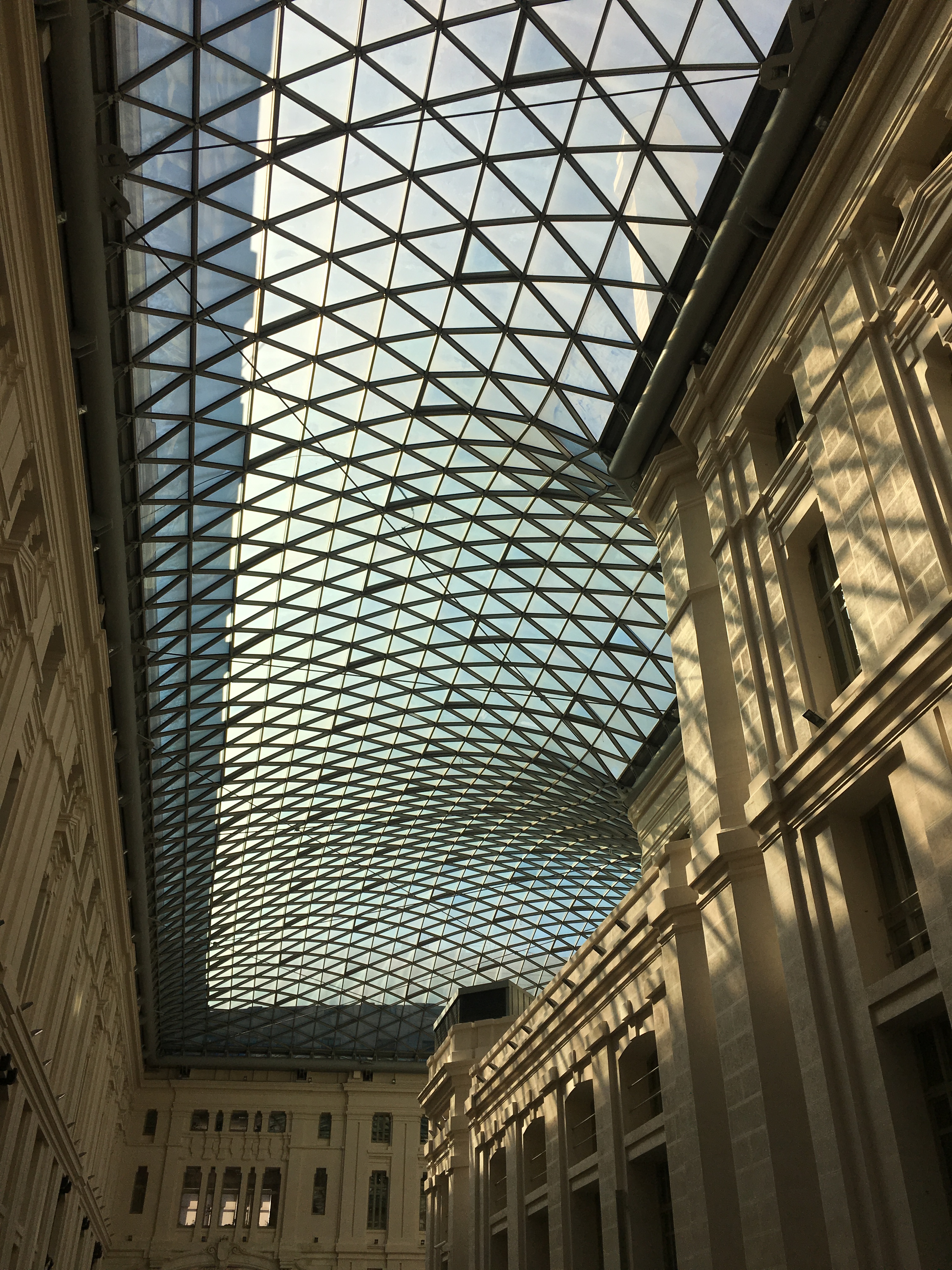
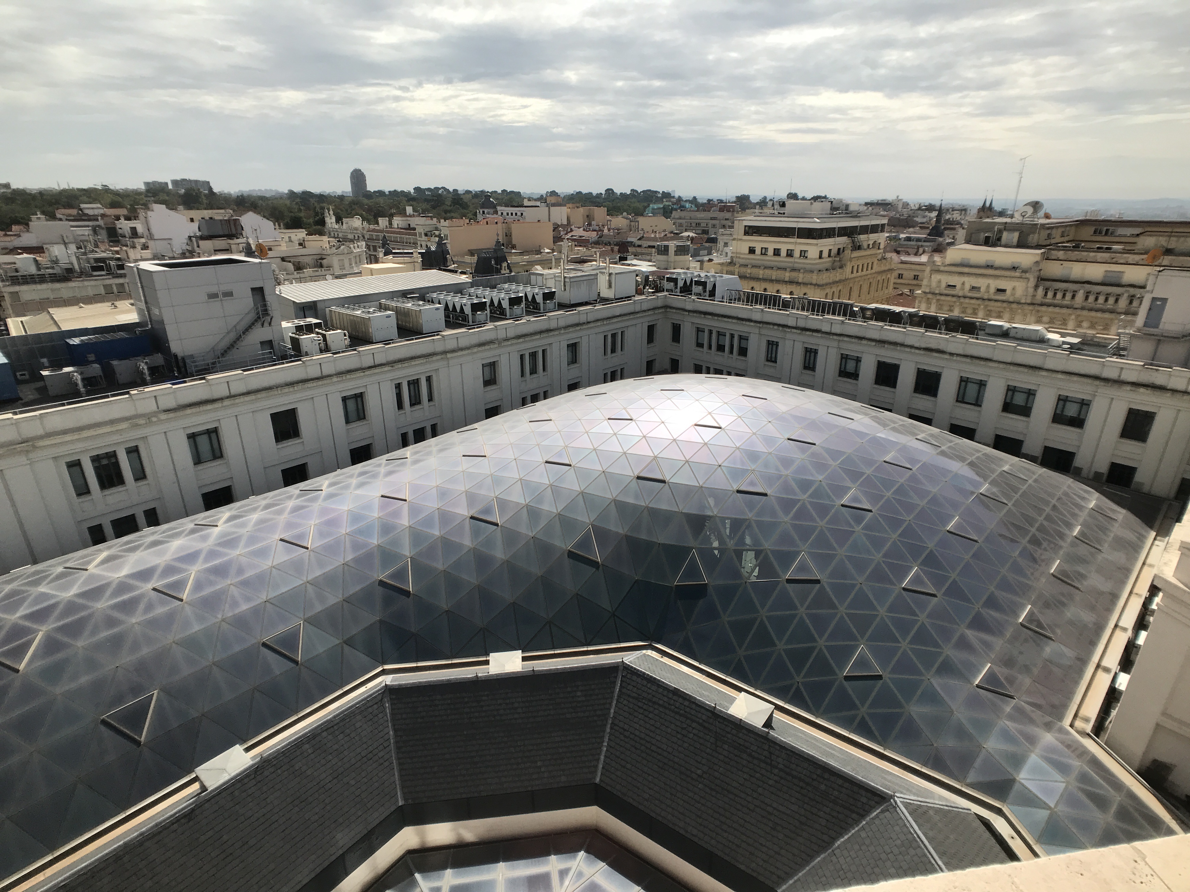
This large roof, built between 2008 and 2009, is a triangular mesh of almost 3,000 m2 and 500 tons in weight resting on existing buildings. However, it transmits the least possible efforts to the old structure thanks to the technique of introducing horizontal cables and a large perimeter beam. With a maximum span of 45 m, it is among the records for single-layer glass covers of this style.
Geometry
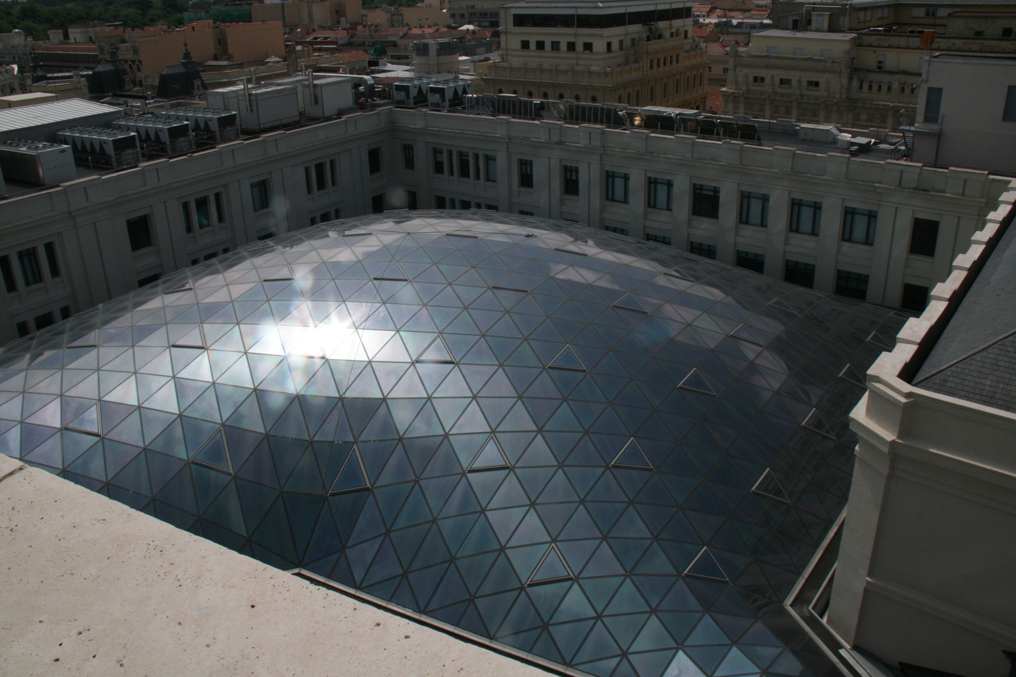
The structure is a single layer triangulated grid shell. Grid shells can be shaped using triangles or quadrilateral (four-sided) facets, although each of them has advantages and disadvantages. Triangulated surfaces can be adapted to any freeform shape, while the use of quadrilateral elements is restricted by some geometric principles (translational surfaces are an example), as they have to be planar in order to keep the budget under reasonable limits. Quadrangular meshes provide more transparency, and fewer mullions, as they eliminate the diagonal one between two triangles).
Because of that, engineers and architects studied both solutions for this project. The main condition was the existing buildings shaping the perimeter of the grid. The edge horizontal beam needed in this perimeter to control the forces transmitted to the old structure led the design towards a triangular mesh, easy to shape with non-curved edges.
The surface was firstly conceived using a balloon that was inflated under 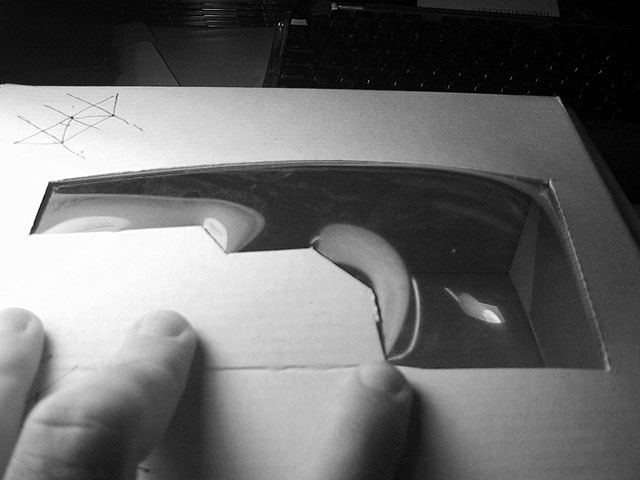
a physical model of the roof opening, letting it describe the shape. After that, using a software for formfinding analysis, the final shape was designed. This kind of analysis try to find the optimal shape so that no bending moments are developed in the structure, this is, loads are resisted by axial forces inside the elements (like in a 2D arch). With this criteria, lightweight and economical structures are designed, as they need less amount of material. Small changes from the ideal surface had to be made, in order to incorporate some visual specifications, but bending moments are very small.
The longest edge of the roof is 100 m, and it spans a maximum of 45 m.
Structural design
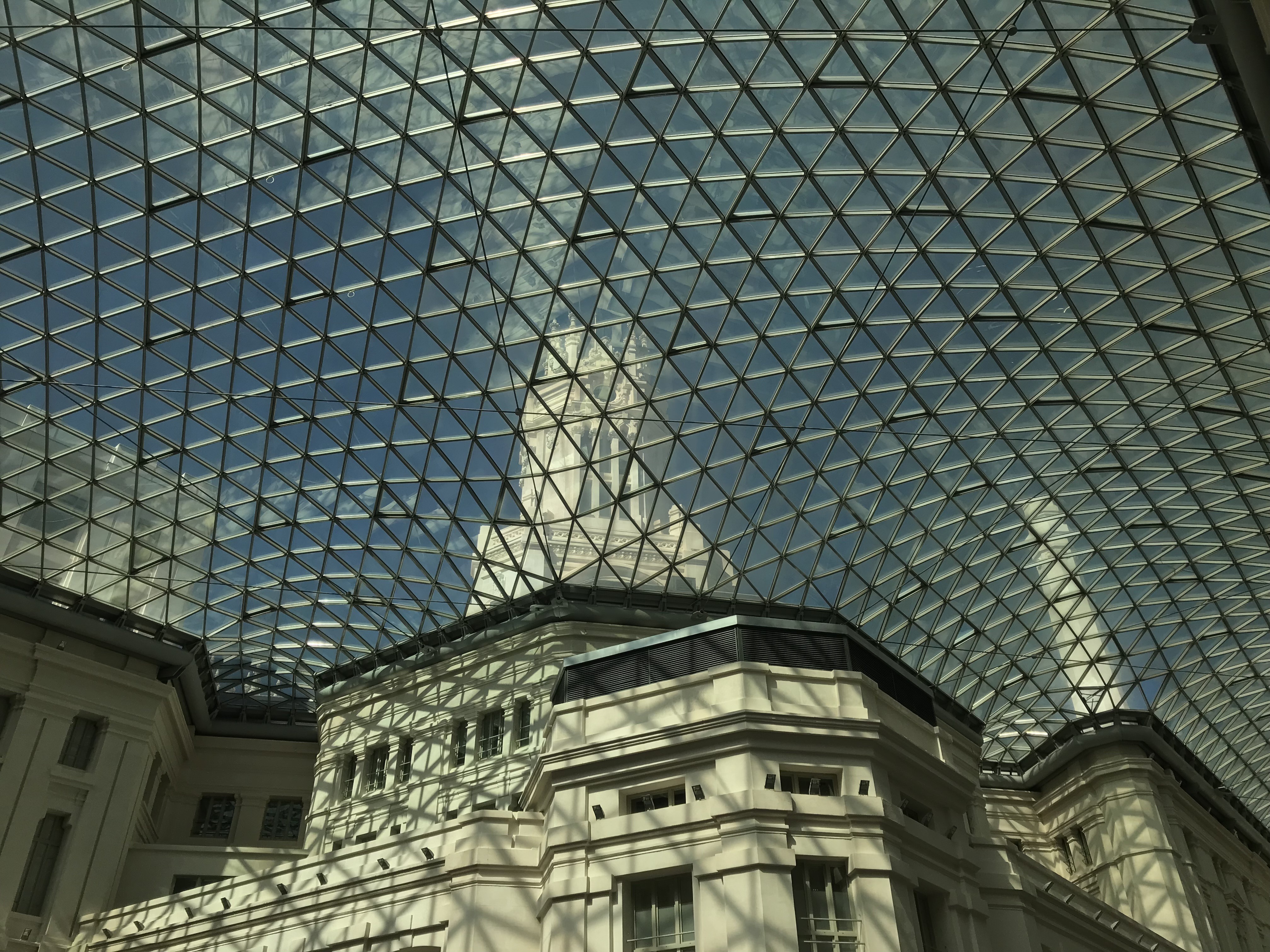
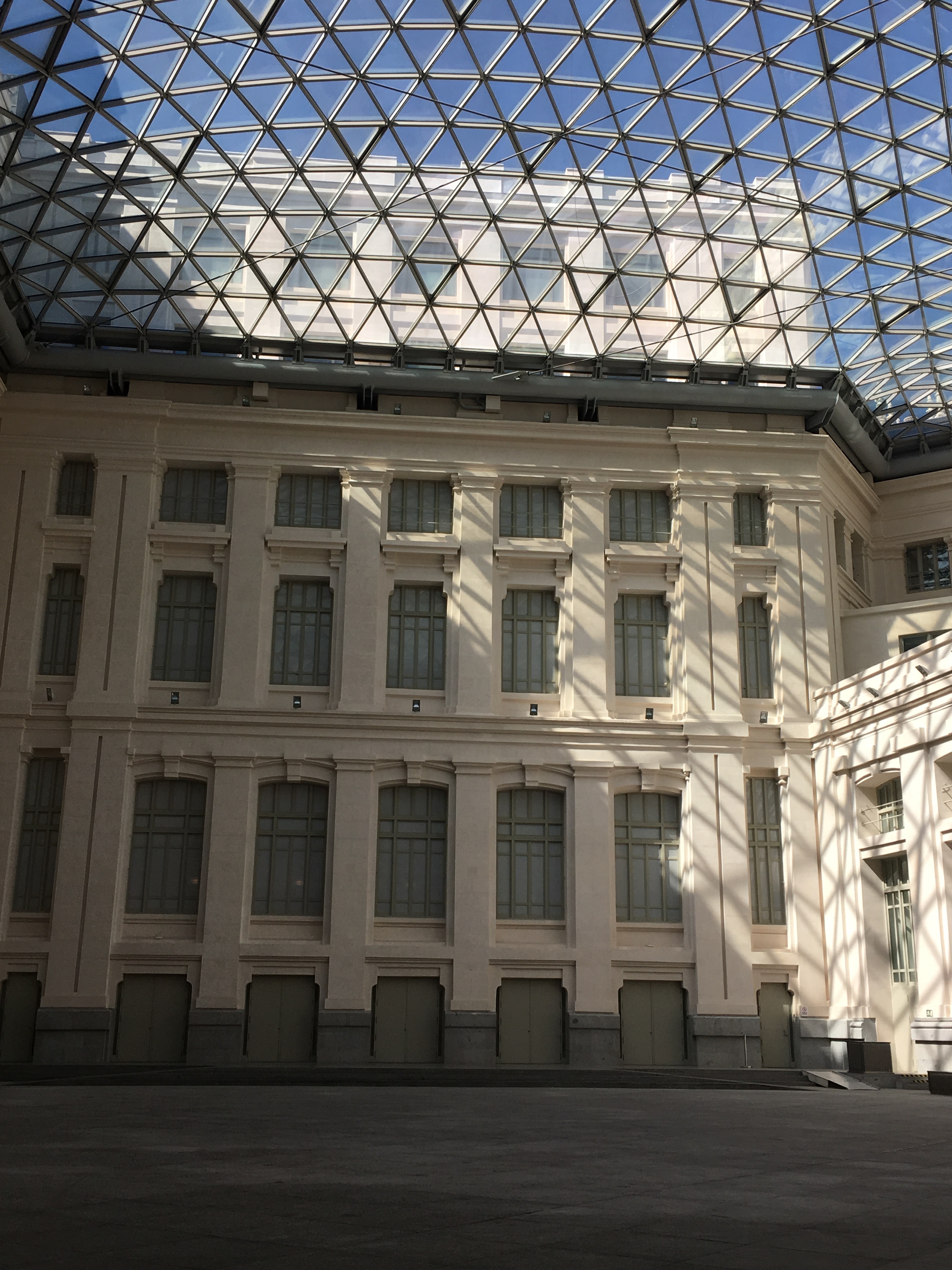
The structure is a single layer triangulated grid shell, whose bars are attached to an edge beam that has a circular hollow steel section with 762 mm diameter and runs along the perimeter of the courtyard at almost 22 m height from the ground. Twelve horizontal cables, with a diameter of 45 mm, hold the shell, in order to avoid transferring horizontal trusses to the 100 years old existing buildings, where the whole structure is supported.
The bearing capacity of the walls is more than enough to withstand the weight of the roof plus the considered live loads. However, high horizontal forces at that level would make them fail if they are not properly reinforced. As the objective was to act as little as possible in the existing buildings, different techniques were used to limit the forces transmitted to them, in addition to the installation of the horizontal cables.
Cavities were carved into the existing brick walls and reinforced by embedded steel boxes. The edge beam is outside the wall (you can see the gray tube from inside the courtyard), but it is supported every 6-8 m by brackets placed inside the cavities. With this, the loads are introduced more or less centered into the existing brick walls, avoiding bending moments. In some areas of the western wall, where there are steel structures, a steel grid instead of the cavities and steel boxes had to be built.
The shell is only horizontally restrained at one point located in the western wall (it was easier to reinforce). Everywhere else, spherical sliding bearings were placed for the brackets of the edge beam.
With this, almost only centered vertical forces were transferred to the supporting walls, and the shell has mainly membrane forces (forces inside its surface).
Connections
The grid bars in the edges of the glass triangulated panels are connected at the nodes by means of a system called SLO, Single Layer ORTZ, by the company Lanik. Usually, these connections are based on one prestressed centric bolt at each end of the grid bar. In order to increase the bending moment capacity of some connections, welding is needed. This process will slow the construction, so a purely bolted system is preferred.
This SLO system consists of two bolts, one on top of the other, which creates the necessary tension-compression couple to resist the bending moment. The con, is that the grid bars height has to increase, giving a final shape of 80×140 mm. Also, prestress is not needed, so the assembling process is easier.
Glass
Glass panels are designed independent of the main structure. They have to withstand their self-weight plus wind, snow and maintenance loads. There are almost 2000 insulated glass panels with a maximum edge length of 2.9 m.
They consist of an upper layer of 8 mm tempered glass together with a lower layer of 2 x 6 mm thermally toughened glass, and are secured against uplift due to wind by special clamps in between the two glass layers, invisible from the outside and inside.
Construction process
The steps followed to build the roof that covers “Palacio de Comunicaciones” courtyard were:
- Installation of temporary working platform at a height of 20 meters above ground covering the entire courtyard, and scaffolding towers.
- The cavities were carved in the existing walls and the steel boxes executed.
- Installation of the edge beam. It was lifted in 6 m long pieces using a crane. All the brackets with their supports were placed into the embedded steel boxes.
- When two-thirds of the roof was completed, it was necessary to realign the structure, due to some accumulated deviations. Provisions for such movements had already been taken into account in the preparation of the construction and all scaffolding towers were equipped with teflon pieces to allow smooth horizontal displacements.
- Welding of the connections between the surface and the edge beam, once the entire grid structure was at its correct position.
- Installation of glasses.
- Installation and tensioning of cables. In this phase, the grid partially uplifted from the temporary scaffolding towers.
- Removal of all towers and scaffolds below the edge beam, following a detailed procedure.
Video
Photos
-

- Formfinding with a balloon
-
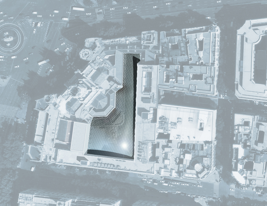
- Plan view
-
- Side length