Introduction
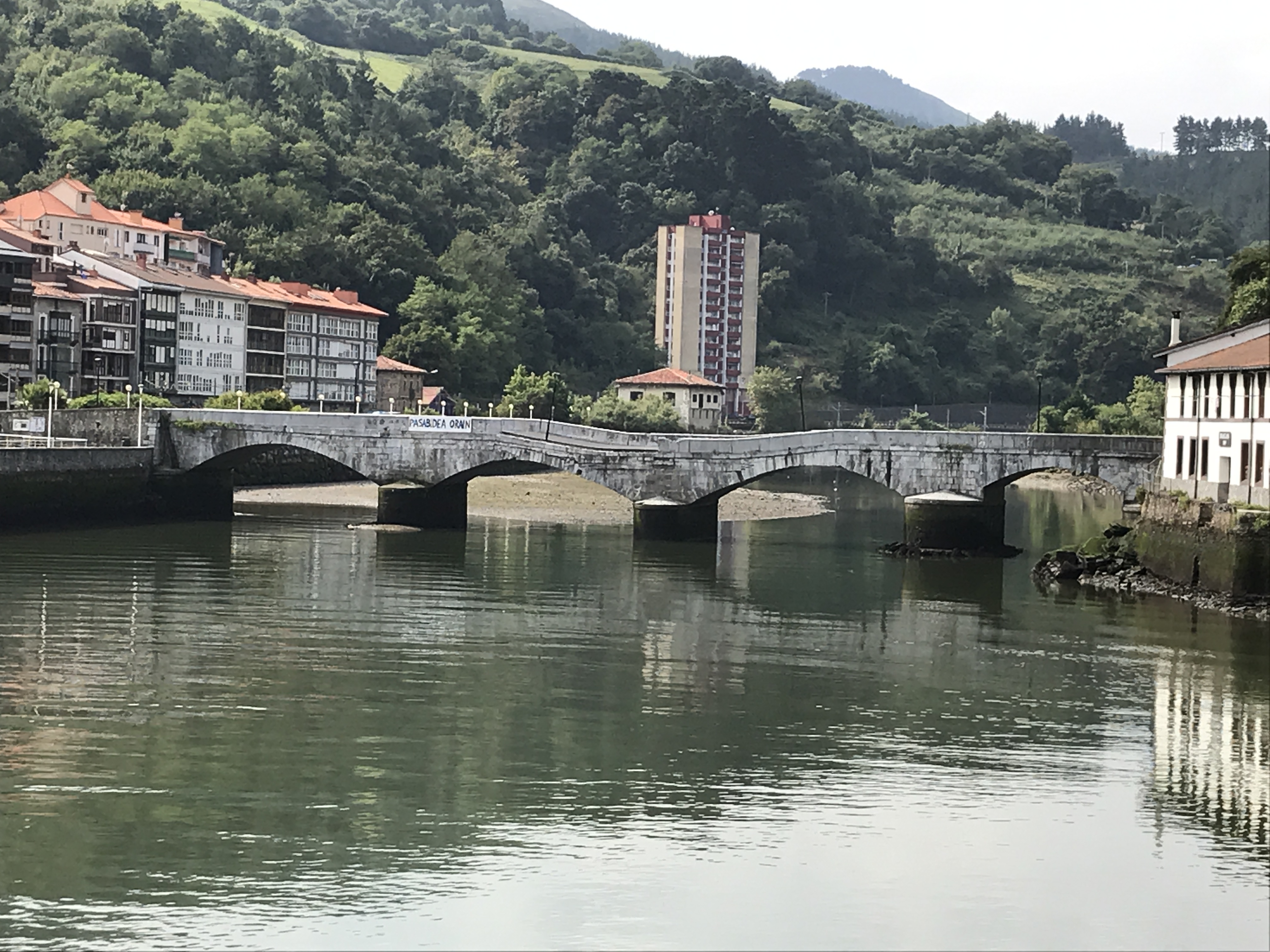
Located in the Spanish Basque Country and crossing the Deba River, the Deba Bridge has served for over a century to connect the coastal towns of Deba and Motrico. Consisting primarily of stone arches, in 2013 it was converted into a pedestrian bridge because another bridge was built for connecting N-634 and GI-638 roads. A work of great hereditary significance for the region, the Deba bridge is described by the Católogo de Puentes de Gipuzkoa Anteriores a 1900 as “the most representative and best-conserved example, at the provincial level, of the bridge architecture of the second half of the nineteenth century.”
In the mid-nineteenth century, a connection between villages Deba and Motrico by way of a coastal route is planned. Achieving this would require crossing the Deba River. On March 22nd 1863, Antonio Cortázar, architect and interim director of public works for the Guipúzcoa region, was directed to bring to fruition the Deba-Mortico route, including the Deba River crossing.
To complete the design, Cortázar gathered further input from the mayors of both towns. The final plans were presented and signed on June 22nd, only 3 months later. The bridge would be a masonry bridge. Winning the construction bid was Luis Emperanza Mancisidor, blacksmith, along with his stonemason and financier, José Joaquín Corta. Two years later, the Guipúzcoa provincial council implemented the final section to the west – a drawbridge, to allow boats to cross. In 1866 the route was completed and the bridge inaugurated.
The most visible change since then has been the elimination of the drawbridge span. Originally of steel construction, the moveable span was replaced by a concrete arch covered with limestone in 1955, giving the overall structure a more uniform appearance. The project to “fix” the drawbridge span was led by the engineer Francisco J. Urquía Zaluda.
In addition to visible changes throughout the bridge’s history, and as a result of severe erosion and settlement of several piers, invisible yet significant rehabilitation work has been undertaken to repair and upgrade the foundation system.
Structural design
Having an overall length of 67 meters, the Deba Bridge is composed of three stone arch spans, each 14.6 m (47’-8”) in length, and a reinforced concrete span of 8.7 m (25’- 6”) (originally the steel drawbridge span). The arch height-to-span ratio of 1:6.6 for spans is typical of 19th century stone masonry bridges. The thickness of the arches is 0.8 m (2’-8”), or approximately 1/18 of the span, is also representative of stone arch bridges of the era. The concrete span 4 has a thickness of 0.7 m (2’-3”). The bridge’s out-to-out dimension is 6.5 m (21’-4”) with 1 m (3’-3”) high stone barriers at both edges. A 30 m (98’-5”) ramp provides access from the Deba side.
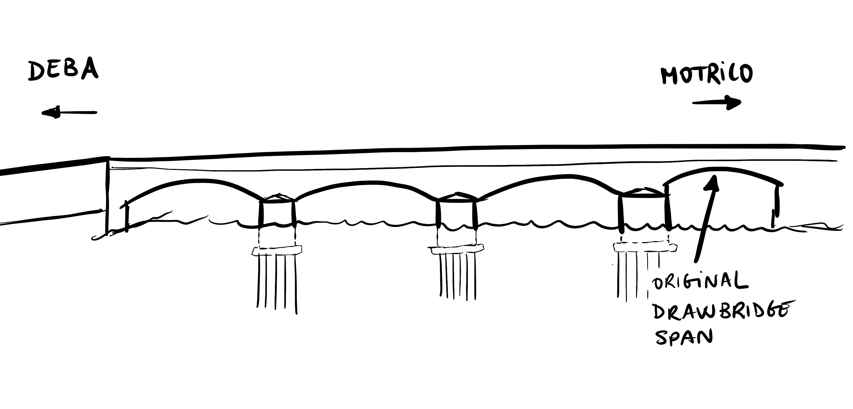
Scheme. Elevation
Three intermediate piers rise to between 4 and 5 meters (13’-0” and 16’-5”) above grade level. The two piers on the Deba side are 3.6 m (11’-6”) wide, exhibiting a pier width-to-span ratio of 4:1 – typical again of “typical” masonry bridges – while the other one is 5 m (16’-5”) wide. This “fat pier” had been necessary to compensate for the imbalance of thrusts resulting from the adjacency of the arch and drawbridge spans.
Foundation
Accounting for the existence of unstable soils and great depth to bedrock, the bridge’s original designers chose to support the piers on a deep foundation composed of wooden piles. The piles used for the Deba Bridge had “a length of five meters (16’-4”) and were at least 20 centimeters (8”) in diameter” (see related book). They were arranged in a grid pattern and were capped by a grillage of wooden beams, which in turn supported a wooden platform on which the stonework of the piers could be constructed. Around the grillage of wood beams was a rubble fill that assured adequate support of the pier above. All of the Deba bridge foundations were of this type except for the west abutment, which bore directly on bedrock.
In order to facilitate pile installation, temporary cofferdams were first established to create dry work areas. The piles themselves were outfitted with cast-iron shoes at the bottom and then driven into the soil by means of After installing the piles, the rubble fill, wooden grillage, and wooden slab were constructed.
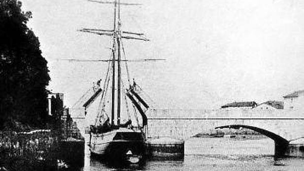
Drawbridge Span
The drawbridge span was comprised of two half bays which could be opened by means of rotating horizontal axles. Maintenance of the lift mechanisms was difficult due to their being located beneath the level of tidewaters. In addition, upkeep of the wooden roadway decking was “very costly, demanding frequent restorations.” Being that “the complete renewal of the drawbridge span, including its adaptation for current loads, would be too expensive and difficult to justify, especially considering that it has n The span was therefore reconstructed as a concrete arch. For visual consistency, the replacement arch was built to the same arch height-to-span ratio as the masonry spans.
The construction process required to “fix” the drawbridge was described in the project as follows:
“In a way that avoids compromising the stability of the moveable span (or of the adjacent arch span?), they will begin by opening several access holes in the abutments to partially support the new arch. Next, concrete will be placed in the chambers […] the formwork will then be constructed and the arch concrete will be poured and let to cure, all the while maintaining the current drawbridge structure and the passage of traffic.
Once the arch has cured…, vehicle traffic will be suspended for approximately 15 days to permit the dismantling of the existing bridge as well as the concreting of the spandrel walls and fill in order that, once given tentative approval, the work can be completed with the installation of imposts and parapets. Pedestrian traffic will be maintained at all times.”
Structural Failure
Throughout its service life, the Deba bridge foundations have suffered episodes of pronounced settlement. In 1883 the piers were subjected to substantial erosion, leaving the wooden piles partially exposed. In response, rubble fill was placed around all of the piers, below the arches. Downward movement of the piles continued, however, leading to especially severe settlement of the first two piers on the Deba side. In 1892 Inocencio Elorza, director of provincial public works, drafted a project consisting of “underpinning, and repairs of “parapets imposts and other damaged components”.
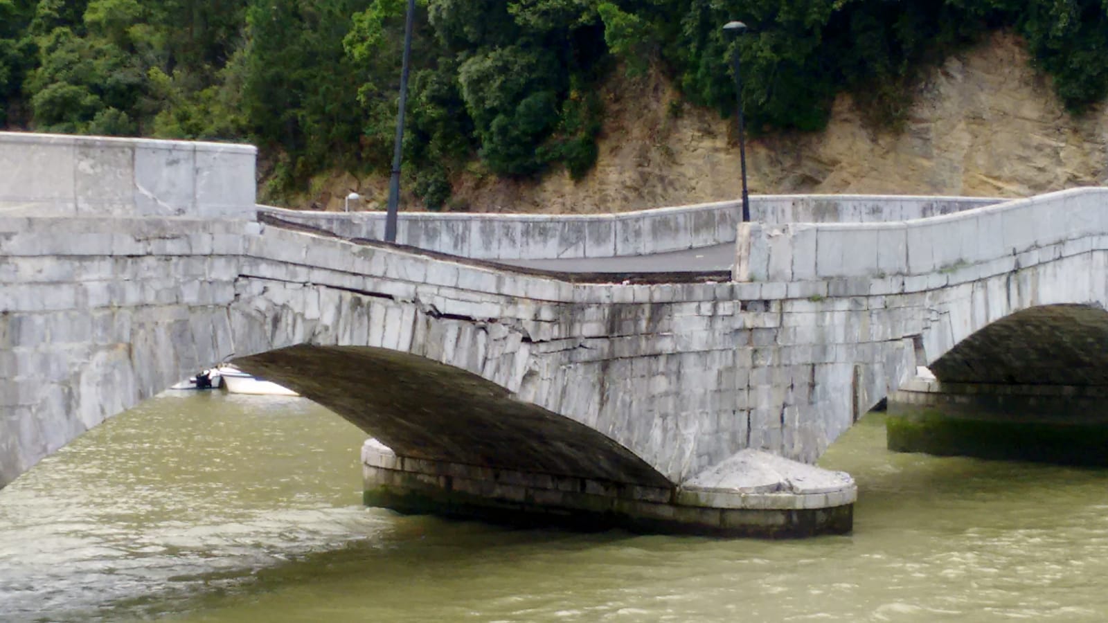
More than 100 years would pass before further major rehabilitation works were again carried out. In 2002 the first pier on the Deba side was underpinned, this time by means of secant piles constructed via jet grouting, because increasing settlements were appreciated. Then on July 5th 2018, the central pier [suddenly] settled one meter and tilted towards the downstream. This resulted in severe damage throughout the structure, leaving the bridge in a state of semi-collapse.
The accepted cause of the pier settlement is an attack on the wooden piles by xylophagus molluscs (teredo navalis), or marine woodworm. Tending to live in open water and not in the soil, these insects affected the piles in the [historically] eroded zones. Their effect was even observed during the 1892-93 repairs: “the woodwork comprising the foundations appears to have been partially degraded by the woodworms which are so prevalent in the ports of this province.” The insects had eaten away at the wooden piles causing loss of strength to the extent that the piles could no longer resist the weight of the structure above.
Related book
Puente de piedra sobre la ría del Deba, breve historia cronológica. Roque Aldabaldetrecu, Javier Castro
Photos
-

- P.C: J.C.Aperribai


-
- Scheme. Elevation
-
- Original drawbridge span
-
- 2018 central pier semi-collapse
-
- 2018 central pier semi-collapse