Introduction
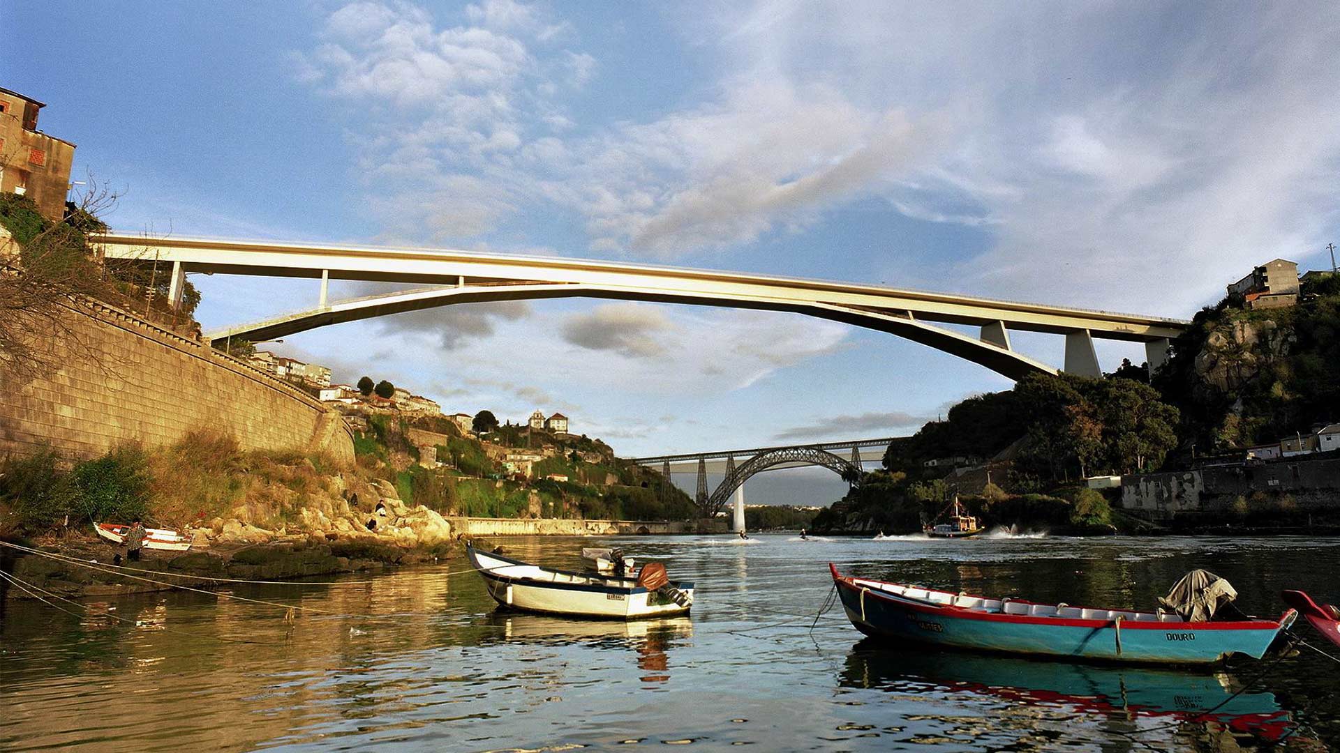
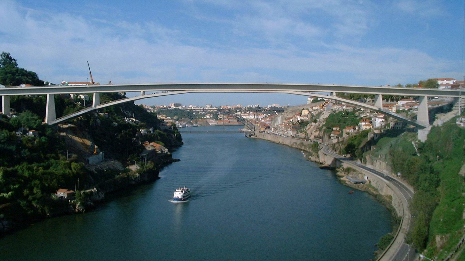
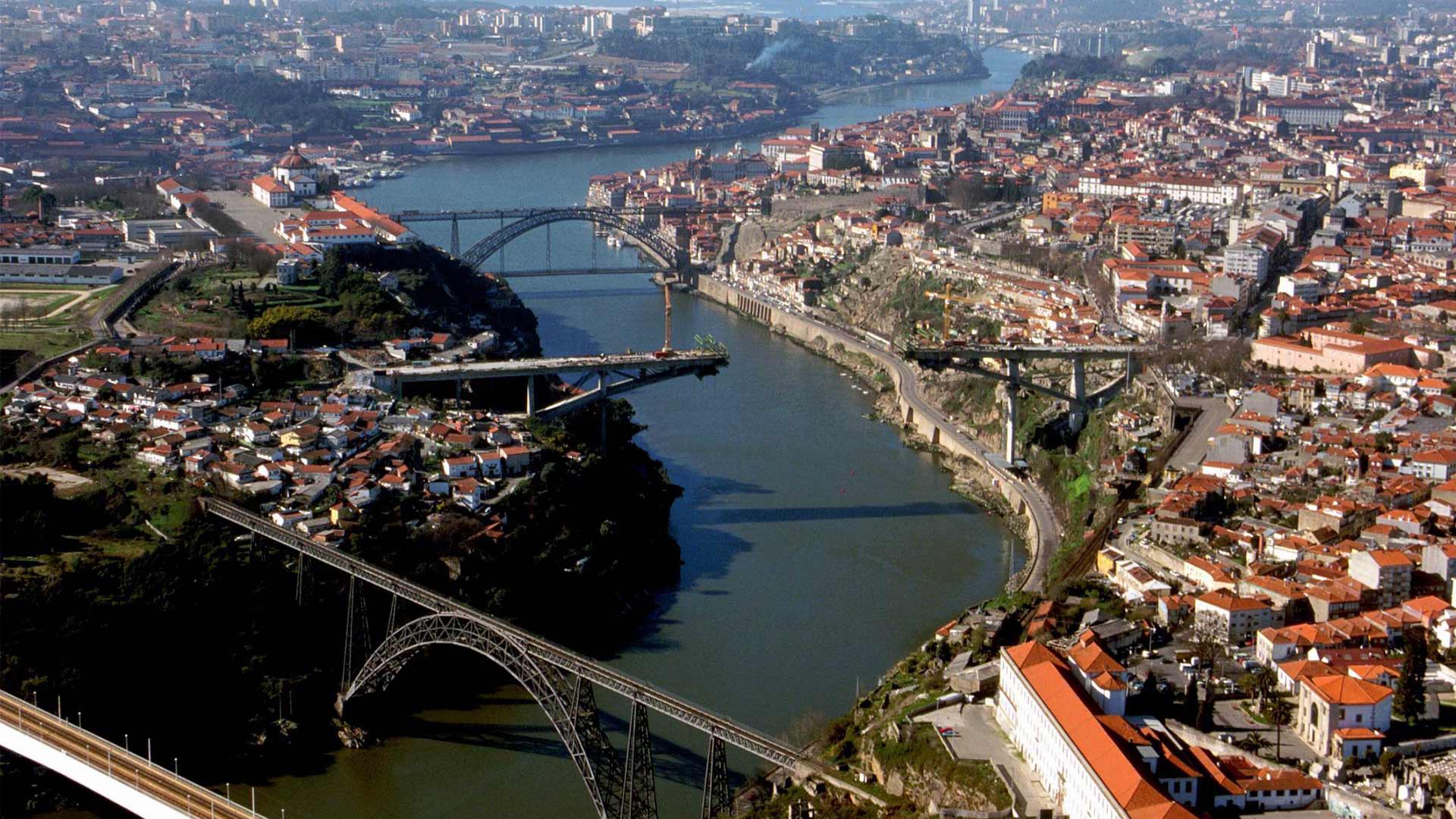
The Prince Don Henrique Bridge, or Ponte do Infante in Portuguese, spans the Duero River connecting the Portuguese cities of Porto and Vila Nueva de Gaia, respectively north and south of the Duero. Located in the coastal northwest of Portugal, Porto is sometimes referred to as the city of six bridges. The monumentality of Porto’s signature bridges is often enjoyed and best comprehended via Duero riverboats.
As the third crossing from the river’s outlet into the Atlantic, the Prince Don Enrique is situated between two historic steel arch bridges. Upstream of the Don Enrique Bridge is the María Pía Bridge, designed by Gustave Eiffel; and downstream is the Luis I bridge, designed by Seyrid, an Eiffel protégé.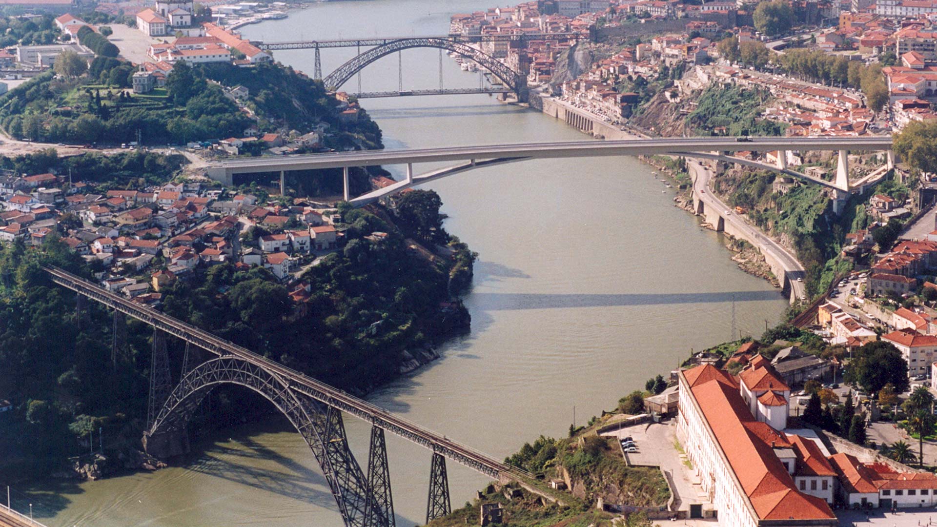
Enrique the Navigator, for whom the bridge is named, was a Portuguese prince and duke. Born in Porto in 1394, he was a key figure in the European exploration of the Americas, and is considered to have laid the groundwork for subsequent Portuguese colonization.
At the beginning of the 21st century, it was decided in planning the Porto Metro that trains would cross the Duero via the upper deck of the Luis I bridge. Roadway traffic, as a consequence, would be routed to a new bridge – the Prince Don Enrique – which opened on March 30th, 2003.
A team of engineers led by José Antonio Fernández Ordoñez was charged with designing the new crossing. The final design would at once innovate by setting a world record for arch slenderness (achieved in the quest to minimize visual impact to existing landscape) while alluding to the design heritage of neighboring historic bridges. In employing post-tensioned concrete, the team sought visual transparency and geometric simplicity, ultimately developing a structure that would recall designs by Roger Maillart, the famous Swiss engineer.
Quite notably, the new bridge would have an arch span-to-rise ratio well beyond conventional ranges (the span being the horizontal distance between arch bases and the rise being measured between arch bases and key). All structures having a similar roadway elevation, the new bridge’s vertical proportions would contrast with the great or camber of the adjacent steel arches.
Geometry
The Prince Don Enrique Bridge has an overall length of 371 meters between abutments, including a main arch span of 280 meters and three side spans measuring between 28 and 35 meters. The out-to-out deck width of 11 meters includes two vehicular lanes in each direction and 3 m wide sidewalks at both edges.

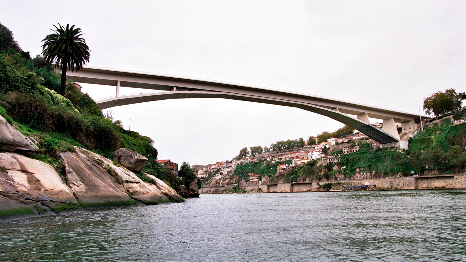
Achieving visual transparency implied placing the arch bases as high as practical up the river banks, which drove the 280 m main span and the relatively small arch rise of about 25 m. The resulting arch span-to-rise ratio of 11.2 exceeds the historic range of between 6 and 10.
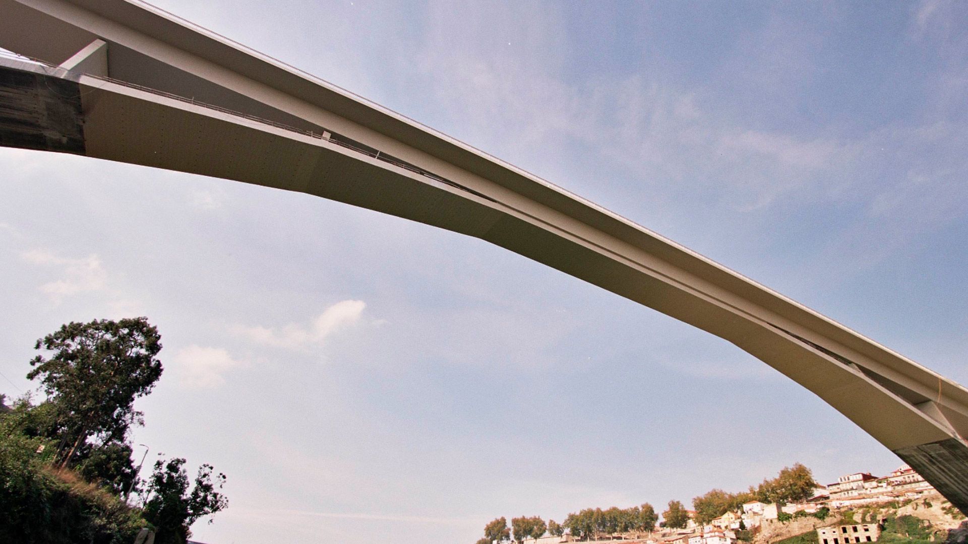
Supported every 35 m by the deck-arch link piers, the bridge deck takes the form of a box in section and has a constant height of 4.5 m and width of 11 m, with 4.5 m lateral cantilevers (box and cantilevers hereafter referred to as the “deck”).
The arch itself has a constant thickness of 1.5 m, resulting in the record-setting slenderness of 186.7 – the conventional range falling between 40 and 90. Instead of curved profile, the arch follows a polygonal longitudinal profile with subtle kinks at each link pier, nearly approximating the antifunicular of the dead loads.
In the bridge’s central 70 m, the deck and arch unite to from a single box section with a height of 6 m. The arch width of 10 m in the central zone increases to 20 m at the arch foundations in order to accommodate the increase in axial forces. The wider arch sections near the bases feature interior voids, which benefit the deck behavior as well as that of the arch during construction.
Structural System
The Swiss engineer Roger Maillart is known for developing two classes of arch bridges: the first characterized by a very stiff deck and flexible arch, and the second having a flexible deck and very stiff arch with hinges at the bases and key. The Prince Don Enrique Bridge, having a deck of great depth and an arch of record-setting slenderness, belongs to the stiff deck, flexible arch category.
As a function of the respective flexural stiffnesses of the arch and the deck of the Don Enrique, the arch functions primarily in compression while nearly all bending moments are resisted by the deck. This load sharing relationship serves in part to compensate for several effects of the arch’s large span-to-rise proportions, including enormous arch axial forces, creep, shrinkage, thermal stresses, and second-order effects.
The deck can therefore be idealized as a continuous beam spanning between the link piers, which behave as elastic supports. This arrangement differs from conventional stiff-arch bridges, in which the arch is very stiff relative to the deck, thereby causing the deck to act as a series of simply-supported beams, resulting in greater bending moments in the arch. In the case of stiff deck / flexible arch bridges such as the Don Enrique, the only significant arch moments are found near the arch foundations and are a consequence of deformation compatibility. These moments are resisted by a special reinforcing detail which guarantee strength and ductility.
Another behavioral phenomenon of the Prince Don Enrique Bridge is the negative flexion produced in the 70 m long central zone (where the deck and arch are united) as a consequence of the eccentricity of the line of action of the arch thrust with respect to the centroid of the box section. The resulting negative flexion effectively compensates for the positive flexion caused by vertical loads on the deck, enabling post-tensioning to be omitted in the central zone. This phenomenon also increases positive moments in adjacent deck spans.
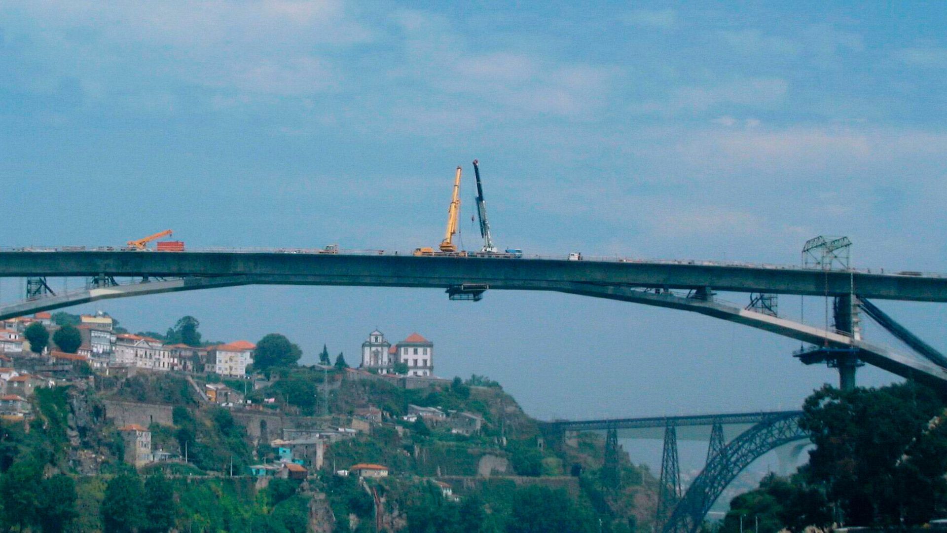
Construction Process
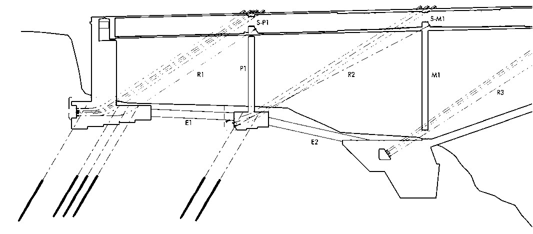
Because the Prince Don Enrique bridge deck has a stiffness similar to that of other segmental concrete box superstructures, a modified cantilever method was employed in its construction. However, given the bridge’s immense span in the permanent condition, the following temporary works were employed until the arch was closed and capable of resisting loads:
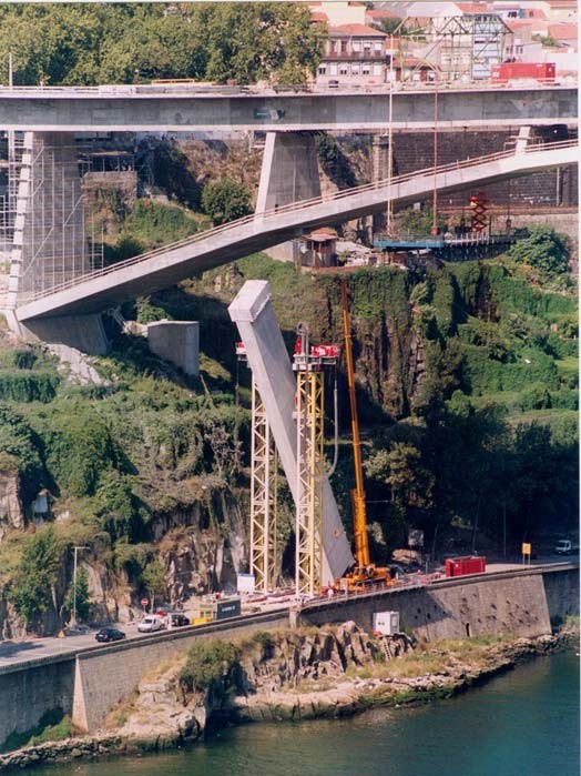
- Concrete piers beneath the first deck-arch link piers. By shrinking the distance between the north and south cantilevers from 140 m to 105 m, the temporary piers decreased the overturning moment by 57%, saving counterweights and terrain anchorage.
- Truss system formed by diagonal cables and link piers as kingposts, and the deck and arch themselves acting respectively as tension and compression chords. Among the advantages of using elements of the permanent structure as a truss is a savings in temporary materials by taking advantage of the tensile capacity of deck post-tensioning, as well as better optimization of the permanent structure because its elements are mobilized as axial force members instead of as a frame.
With temporary works in place, the deck and arch were simultaneously advanced with a pair of specially designed traveling forms – the arch traveler being suspended from that of the deck. In order to minimize bending moments in the arch prior to it’s being compressed under the dead load of the completed structure, the arch was suspended from deck-pier joints with Dywidag bars (which were also used to hang the arch traveler from that of the deck).
As the superstructure advanced towards mid span, the loads imparted to the foundations progressively increased, requiring greater anchorage to the river banks. Beyond the restraint provided by the dead weight of the abutments, piers, and deck of the approach spans, anchorage to the granite river banks was achieved with temporary post-tensioned anchors.

Temporary supports were removed following closure and sufficient strength gain of the arch. The design was calibrated so as to preclude both the need for jacking as well as the need to compensate for elastic shortening of the arch in compression.
At 45 m tall and weighing 750 tons each, the temporary concrete piers were removed using a specially designed system engineering by Mamoёt. Supported by two steel towers, the piers were first rotated in plan before being laid horizontally, parallel to the river, and cut into smaller sections for transport from the site.
The following quantities were provided by the designers:
- Total weight of structure just prior to arch closure: 750 kN/ml (380 kN/ml in the central 35 m)
- Compressive force in the arch just before closure: 260,000 kN
- Compressive force in the arch after removal of temporary supports: 270,000 kN
- Force in terrain anchorage: 11,800 kN (Porto side) and 6,400 kN (Gaia side)
- Compressive force in grade beams: 105,200 kN (Porto side) and 75,000 kN (Gaia side)
- Maximum load in temporary concrete piers: 85,000 kN
Materials
- C50 concrete in deck, piers, link piers,
- C60 and C70 concrete in the arch. Higher strength achieved through the use of silica ash.
References
“Proyecto y construcción del puente arco Infante Don Henrique sobre el río Duero en Oporto”
A MATUTE L.; y Bastos, R.: “The Infant Henrique Bridge over the River Douro, in Porto, Portugal”. In: Fédération Internationale du Béton. Proceedings of the 2nd International Congress. (June 2006)
http://www.ideam.es/ideam_projects/bridges/puente_infante_d_henrique_sobre_el_rio_duero/
http://www.afaconsult.com/portfolio/145921/127/infante-d-henrique-bridge