Introduction
Building a bridge crossing the 3 km of the Corinth Gulf’s strait was a dream for Greece since 1889, when the Prime Minister, Harilaos Trikoupis, spoke about it in the Parliament. But it has not been feasible until 100 years later.
The invitation to tender was in 1991, which ended up with the signing between Greece and the consortium GEFYRA, formed by 6 shareholders, of the Concession Contract for the Design, Construction, Financing, Maintenance and Operation (during 42 years) of the Rion – Antirion Bridge. It took 2 years to get the funds (private finance) and construction started in July, 1998.
The inauguration was hosted by the Minister of Public Works on August 12th, 2004, in the eve of the Opening of the Athens Olympic Games.
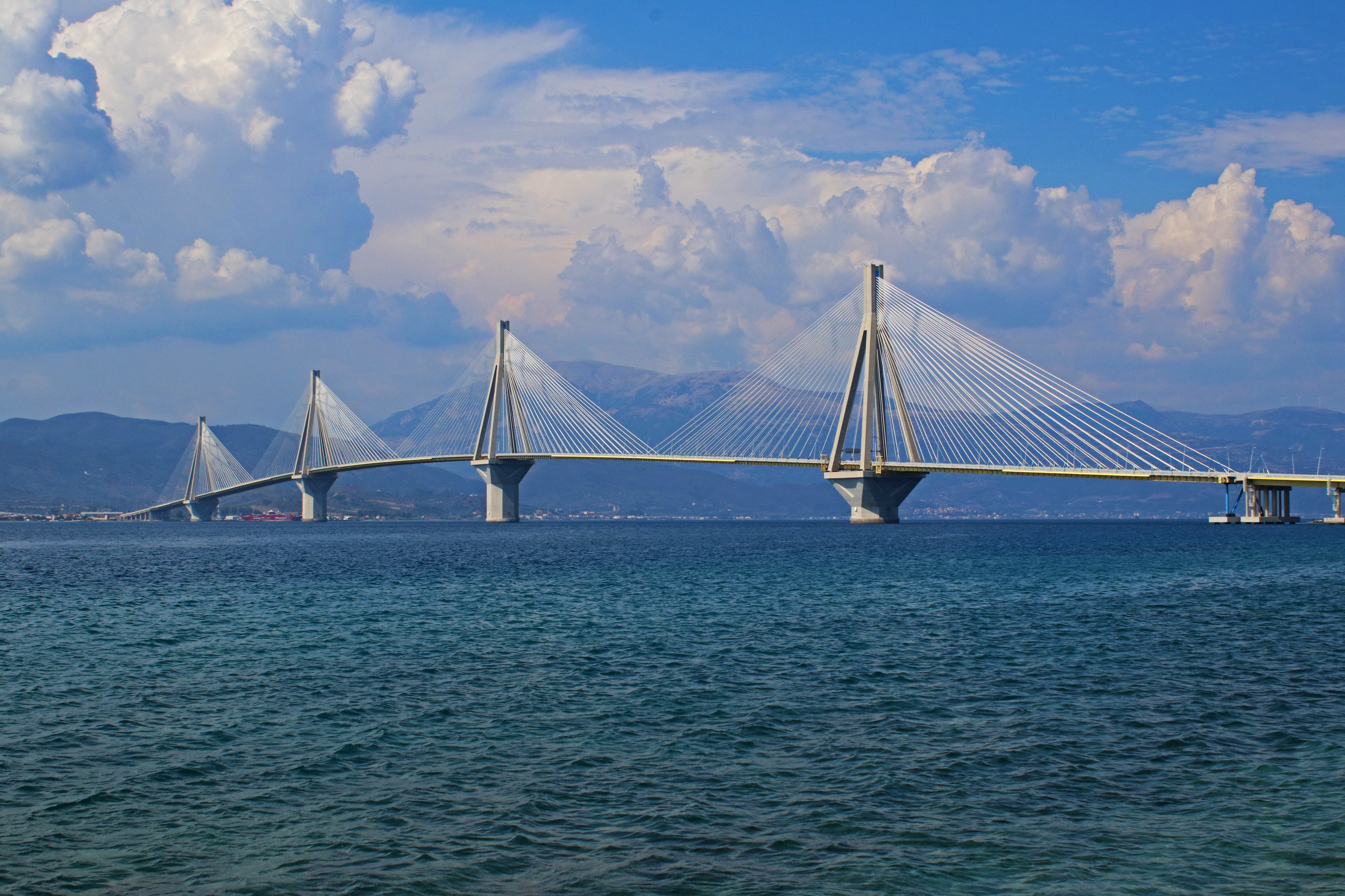
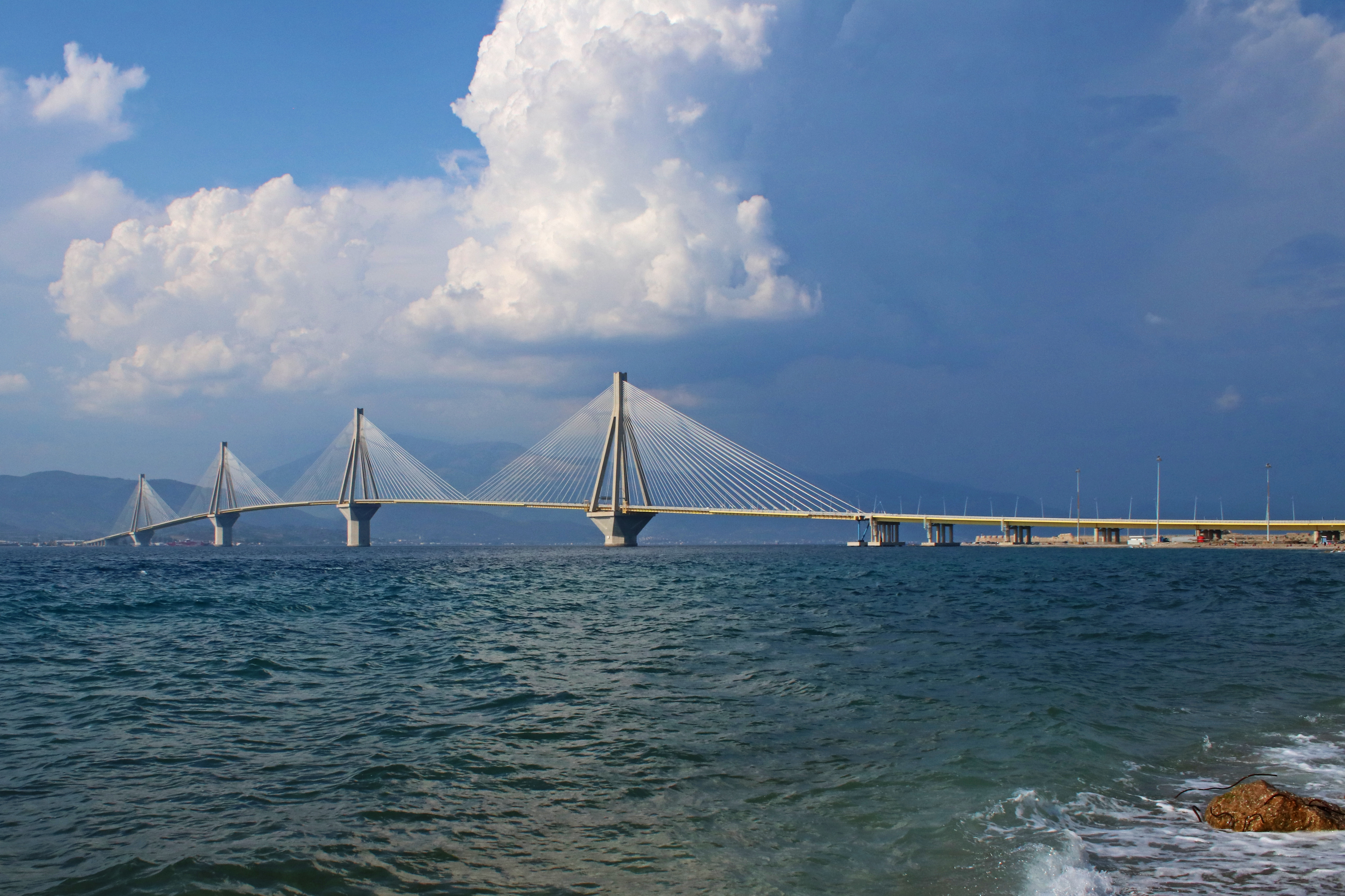
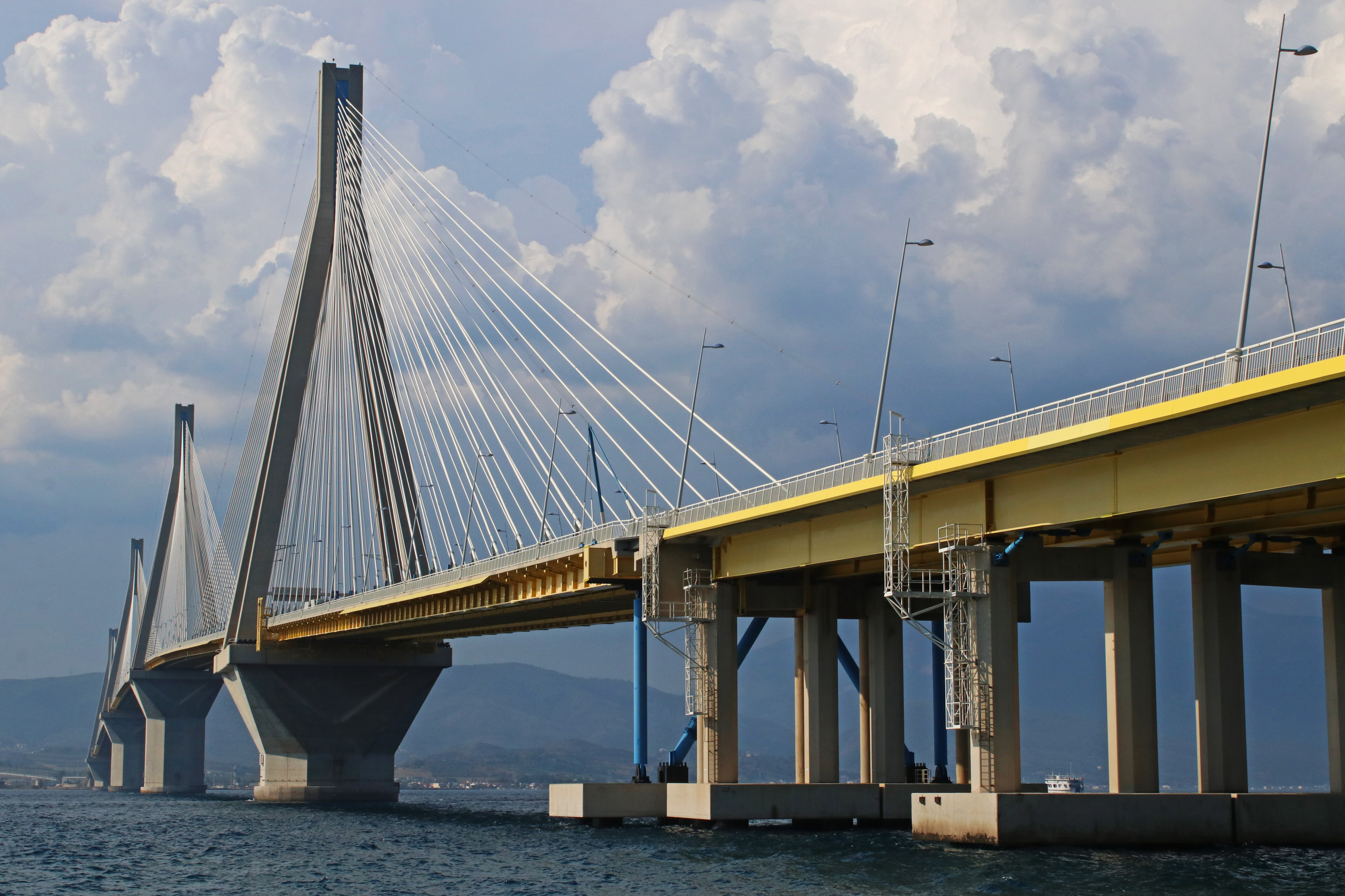
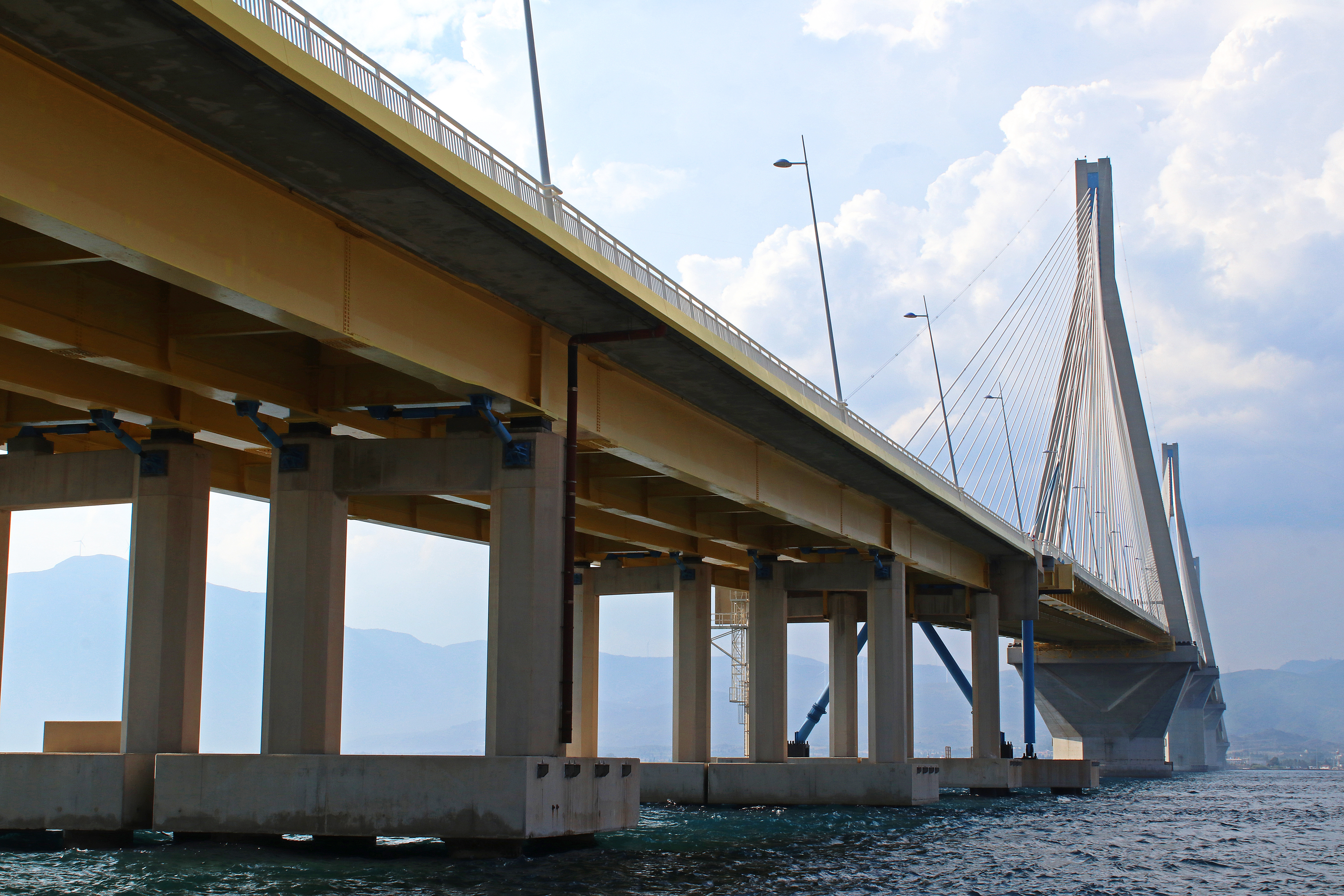
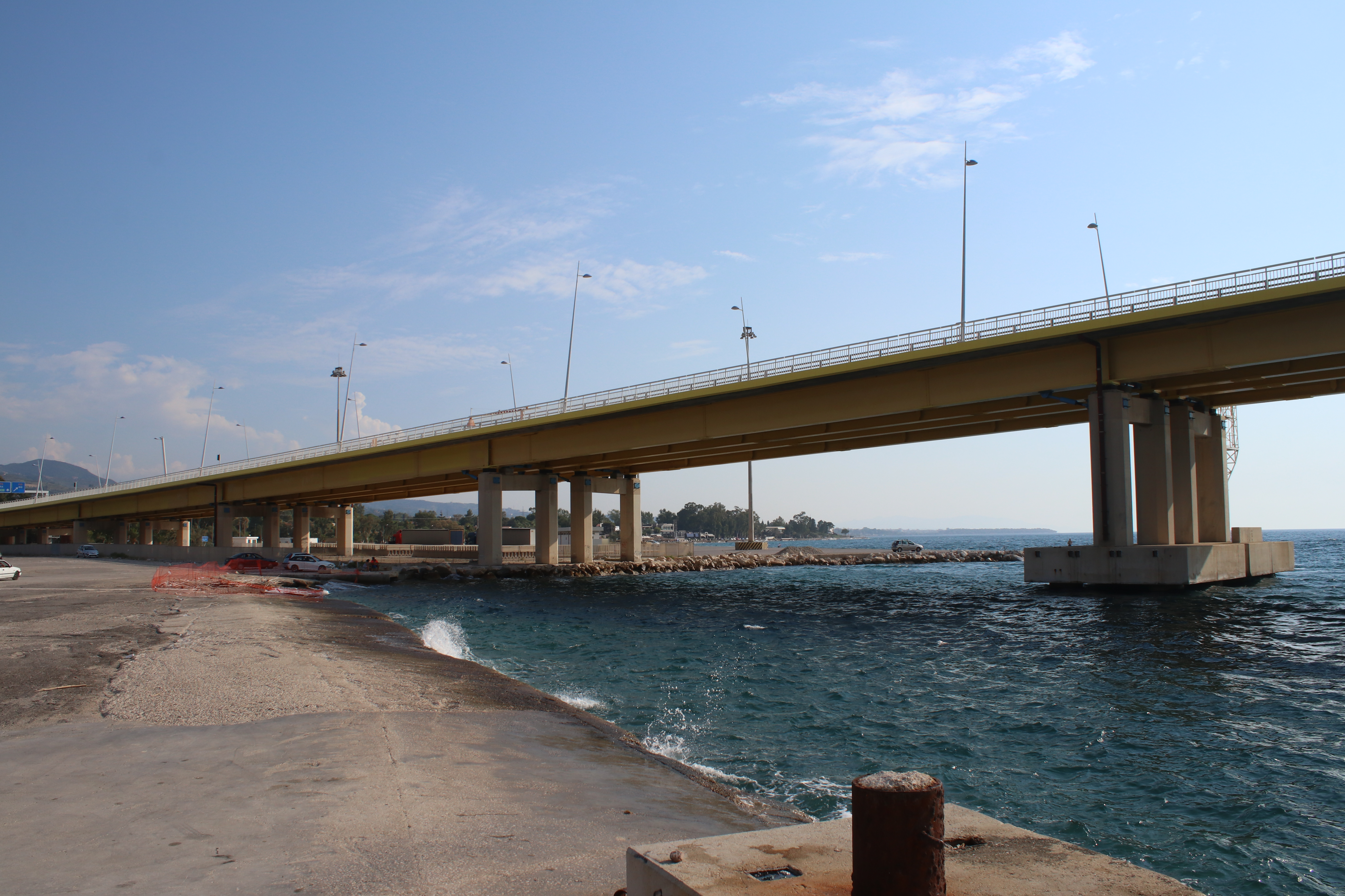
The bridge constitutes a fixed link between the Peloponese, through the city of Rion, and the continent, through the city of Antirion. The engineers designed a main bridge, which is a multi-span cable-stayed bridge 2252 m long, with four pylons, 3 central spans 560 m in length and 2 side spans 286 m long. There are also two approach viaducts, separated from the main bridge by expansion joints, with 392 meters on Rion side (composite deck) and 239 meters on Antirion side (prestressed simple supported beams).
Let’s take a look at this great project.
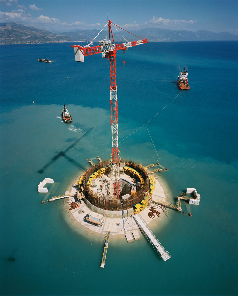
Main challenge: the foundation
Engineering for the foundation design was a huge challenge.
- Seismic hazard. The bridge crosses the Gulf of Corinth, one of the highest seismic areas in Europe. The project seismic requirement was to design the bridge for a 2,000-year return period, which means that there is a 5,8% probability of exceedance for the service life of 120 years.
- Tectonic movements. Since prehistoric times, when the earth’s crust shifted the Peloponnese away from mainland Greece, the Peloponnese peninsula moves away from the continent by a few millimeters each year. The bridge must accommodate a 2 m differential tectonic displacement in any direction and between any two piers.
- Ship impact. Boats navigate under the bridge, and they can collision against one of the pylons. So they and their foundations have to be designed to resist the impact of a big vessel (180 000 tons) hitting the pylon at a speed of 30 km/h and 70 m above the foundation level. This is a force of 480 MN and overturning moment of 34 000 MNm.
In addition to all of this, the water depth in the middle of the strait reaches 65 m and the soil is weak, consisting in alluvial, silty and sandy layers. No bedrock was encountered during the investigations.
And… they decided to use shallow foundations, that is, ¡no piles! But engineers had an innovative idea: they would not support the bridge right on the existing poor and weak soil, but they would treat it, and improve it, to make it strong enough to resist the loads coming from the new bridge and limit the settlements to acceptable values.
A technique derived from offshore engineering was incorporated: the use of driven steel tubular pipes, called “inclusions” (remember, not piles). Some numbers here for this natural ground reinforcement:
- The total number of inclusions under each foundation is of the order of 150 to 200.
- Steel pipes are 20 mm thick, 25 to 30 m long, and have a diameter of 2 m!
- They are placed at a grid of 7 m x 7 m below and outside the foundation, covering a circular area of approximately 8 000 m2.

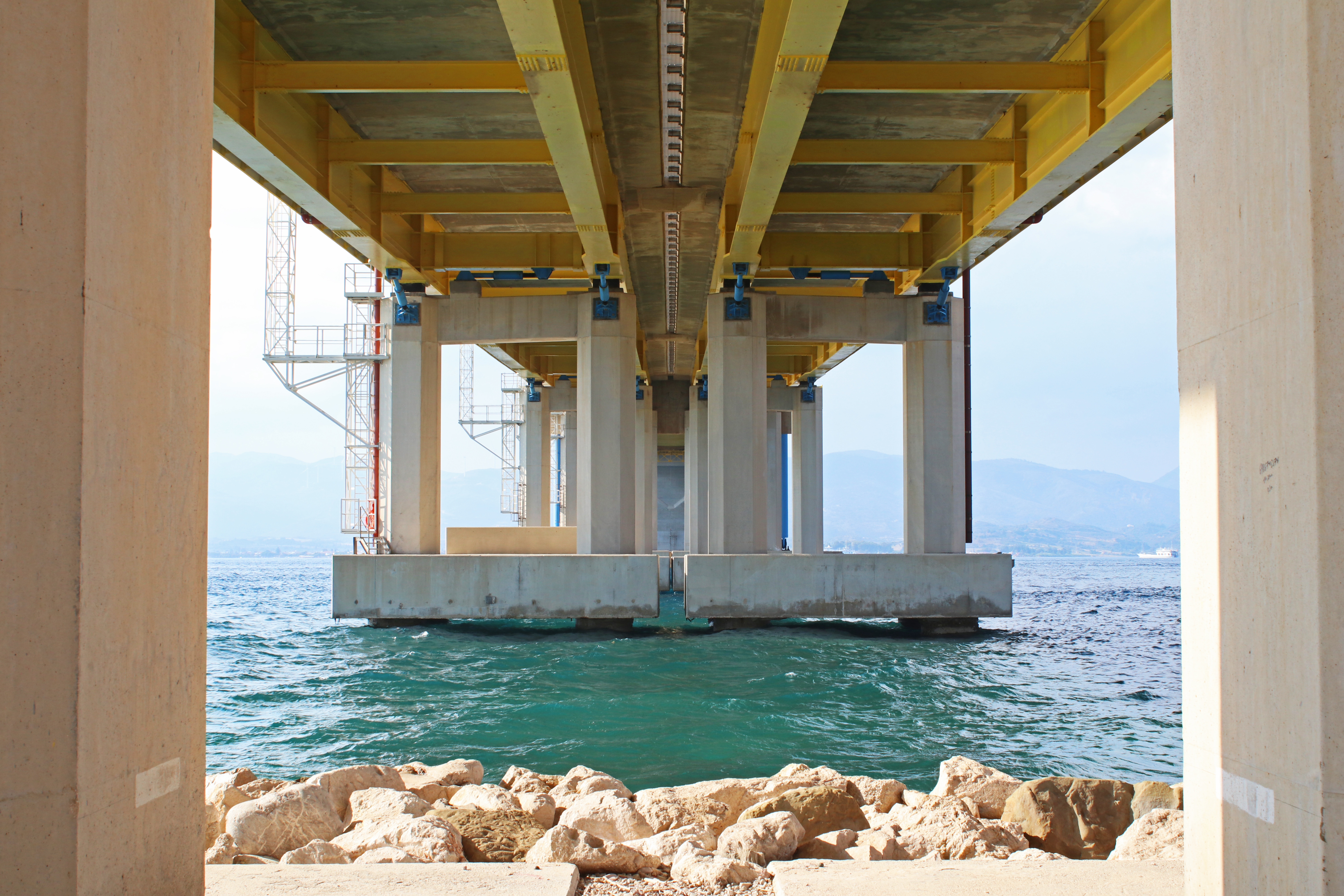
On top of the inclusions, a gravel bed layer, 2.8 m thick, is placed, in order to minimize differential settlements and dissipate energy during seismic events. A gravity concrete caisson (90 m in diameter at the sea bed level plus a saft 60 m tall) rests on top of it, being the under part of the pylons.
This reinforcement scheme is implemented under three of the four piers. Pier M4 (the closest to Antirion, mainland Greece) rests on a 1 m thick ballast layer which is on top of a 20 m thick natural gravel layer without soil reinforcement.
The concept “inclusions plus gravel layer” introduces the capacity design theory in foundation engineering (Pecker & Salençon 1998). Capacity design is based on the dissipation of energy by the ductile failure of some elements of the structure, allowing deformations. In this case, it is used to improve the seismic behavior of a shallow foundation: the gravel layer is equivalent to the “plastic hinge”, which helps with the dissipation of energy by inelastic deformation, and the “overstrength” is provided by the ground reinforcement (inclusions) preventing rotational failure modes. So the allowed failure mode is the sliding of the pylons on the gravel layer. Not actually a problem for the bridge, as it was designed for much larger tectonic displacements! So, the design implies that the foundation will experience permanent displacements after a seismic event.
Other structural data
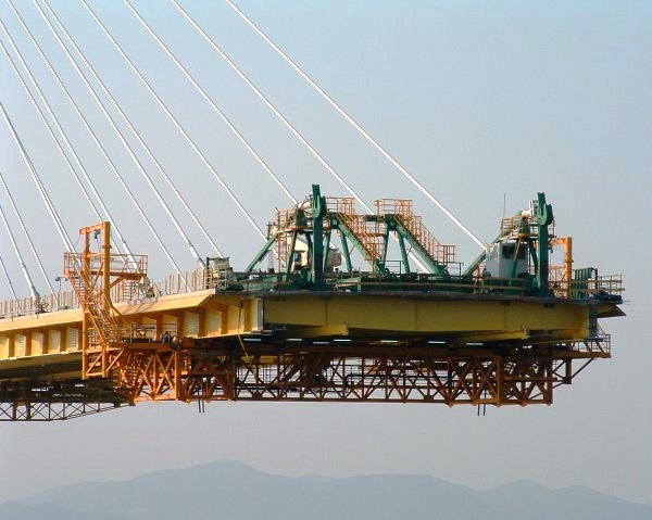
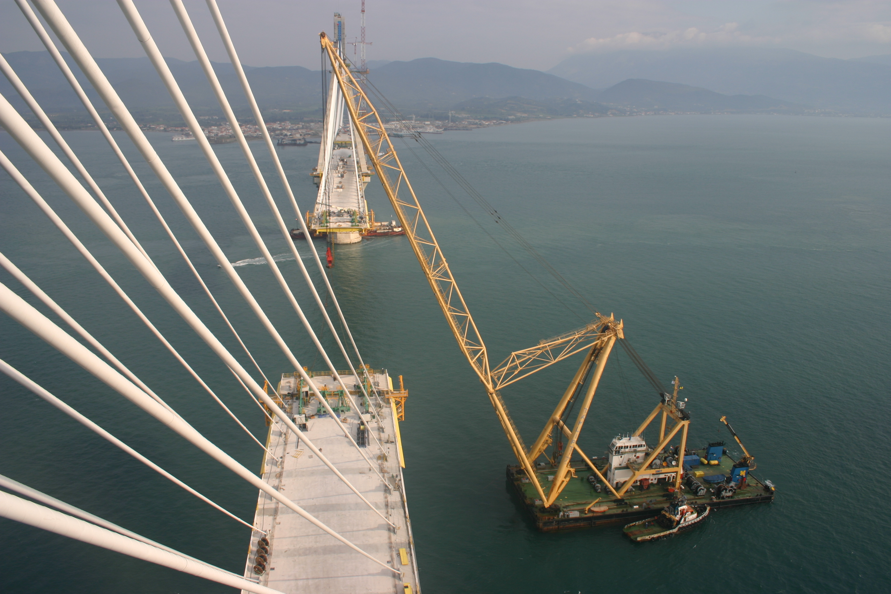
- Deck: it is continuous and the longest in the world (2252 m). But this is not the most incredible thing. Can you believe that it is fully suspended? This means that it is not supported at the pylons or at any other point but hanging from the cables. This helps to isolate it from the rest of the structure when seism comes.
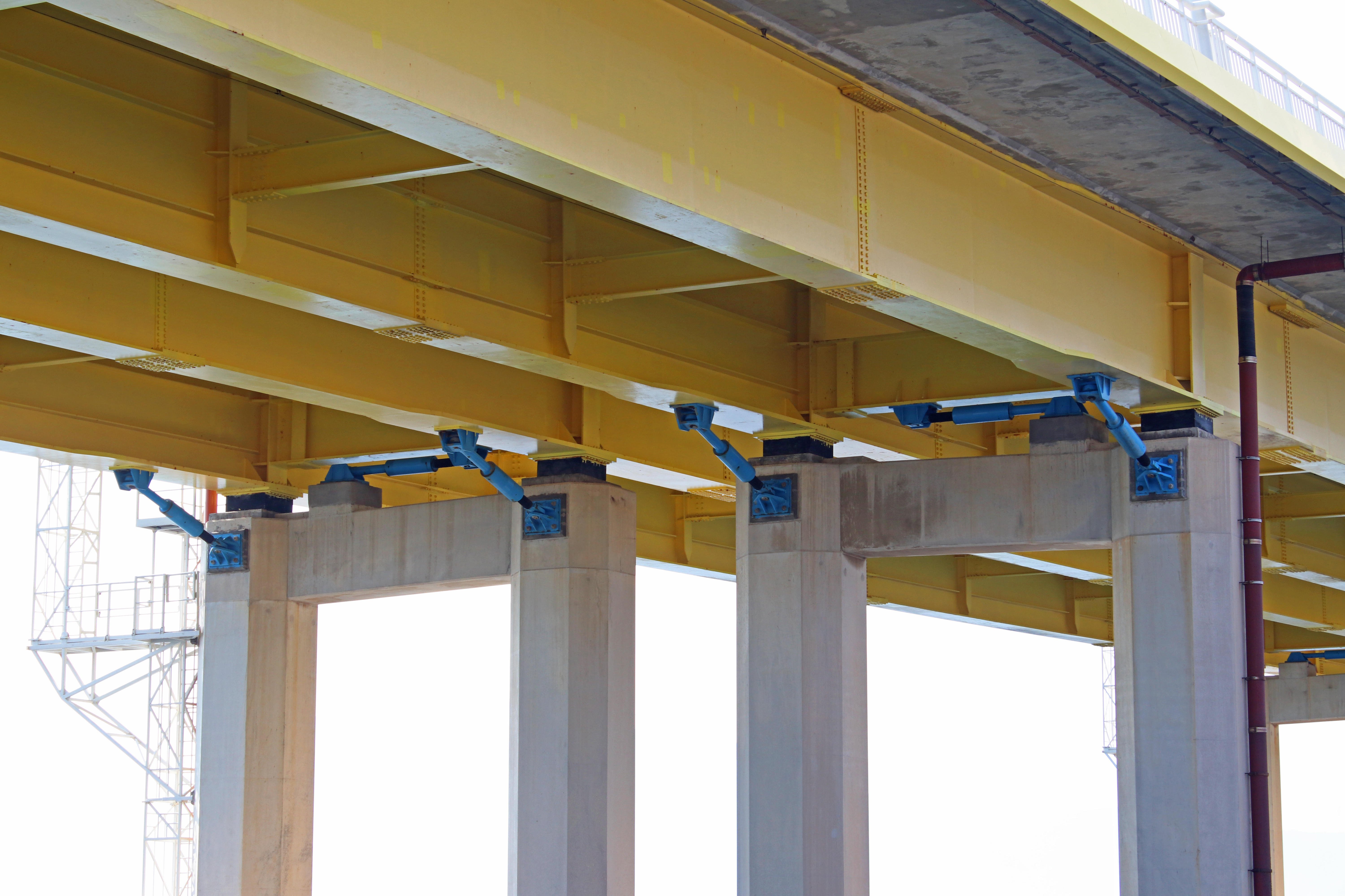
- Deck elements are 12m long, composite and 27 m wide. The concrete slab is 25-35 cm thick, connected to twin longitudinal steel I-girders, 2,20 m high, braced every 4 m by transverse cross beams.
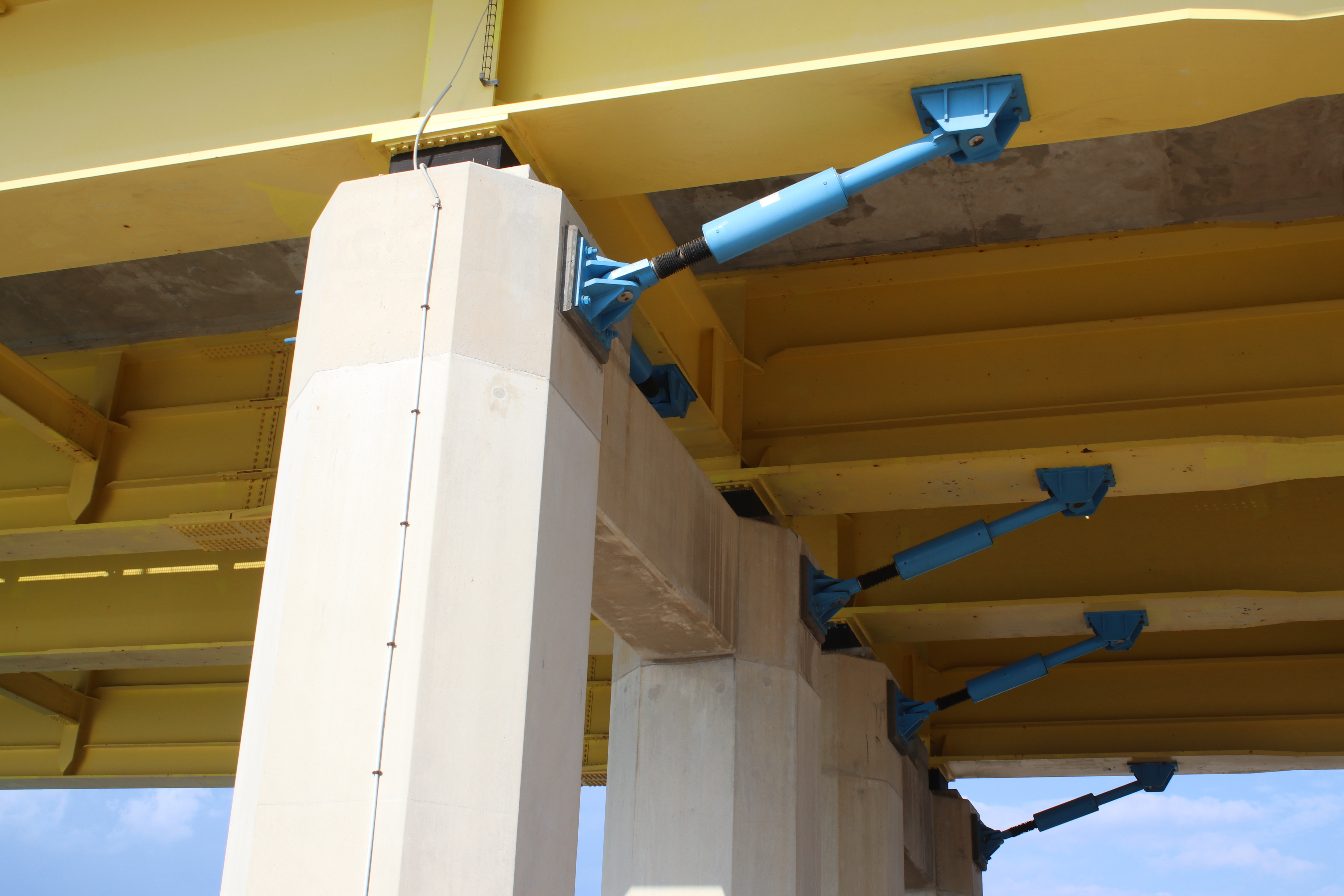
- Dampers are used in order to dissipate energy and reduce lateral movements of the deck during a seismic event. The deck is transversally connected to the pylons by 4 hydraulic dampers, and by 2 to the transition piers. The connection is made by horizontal metallic struts, which keep the deck in place when wind blows, protecting the hydraulic dampers which will only act during a seismic event. For it to happen, these struts, called fuse restrainers, break due to the big seismic action, and so dampers can work.
- The “abutments” are steel frames hinged on their ends, that is, they can rotate to accommodate all thermal and tectonic movements. Between the main bridge and the approach viaducts, expansion joints are placed. Maximum movements at service are around 1,2 m opening and closing in longitudinal direction, going up to more than 2,3 m during an earthquake.
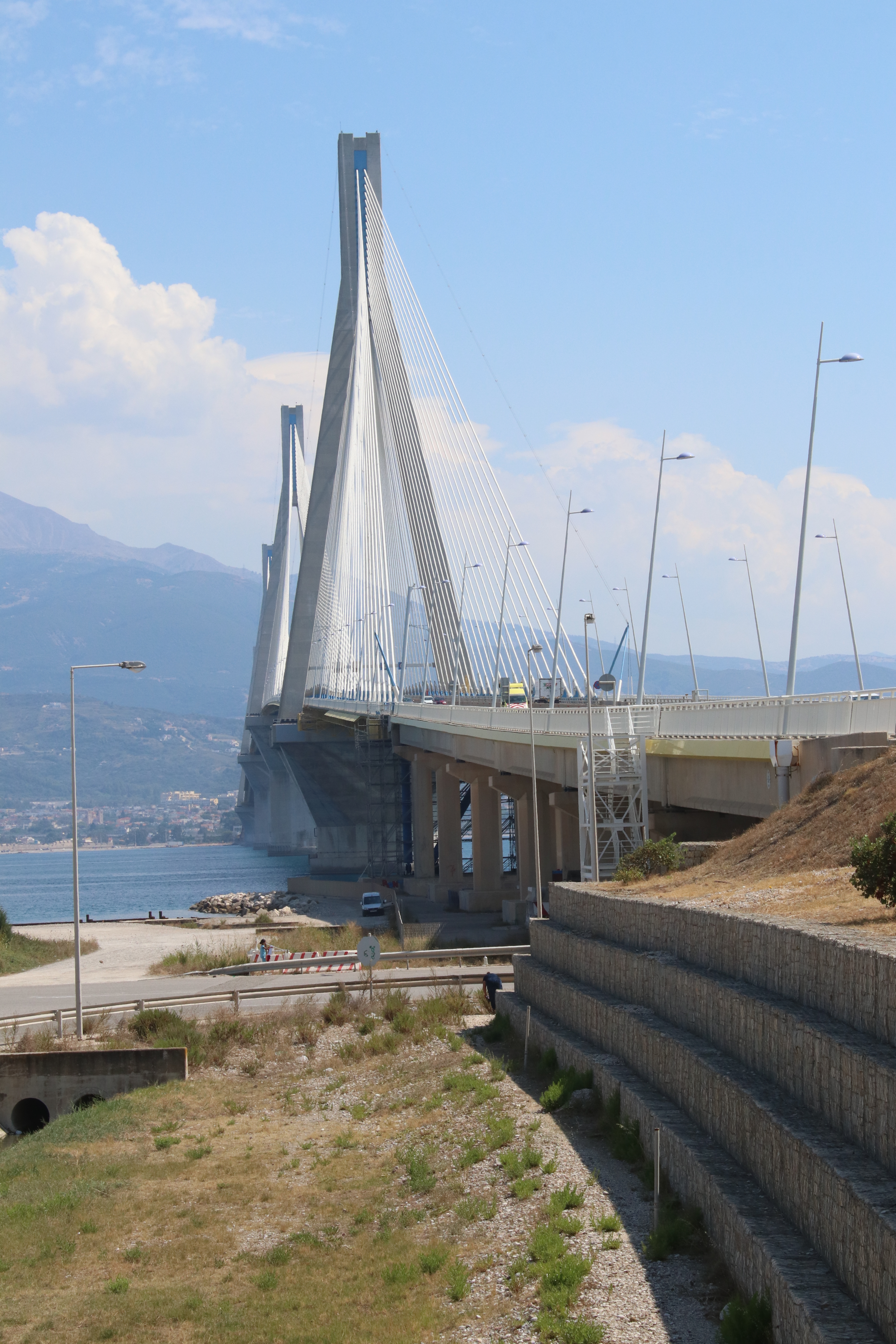
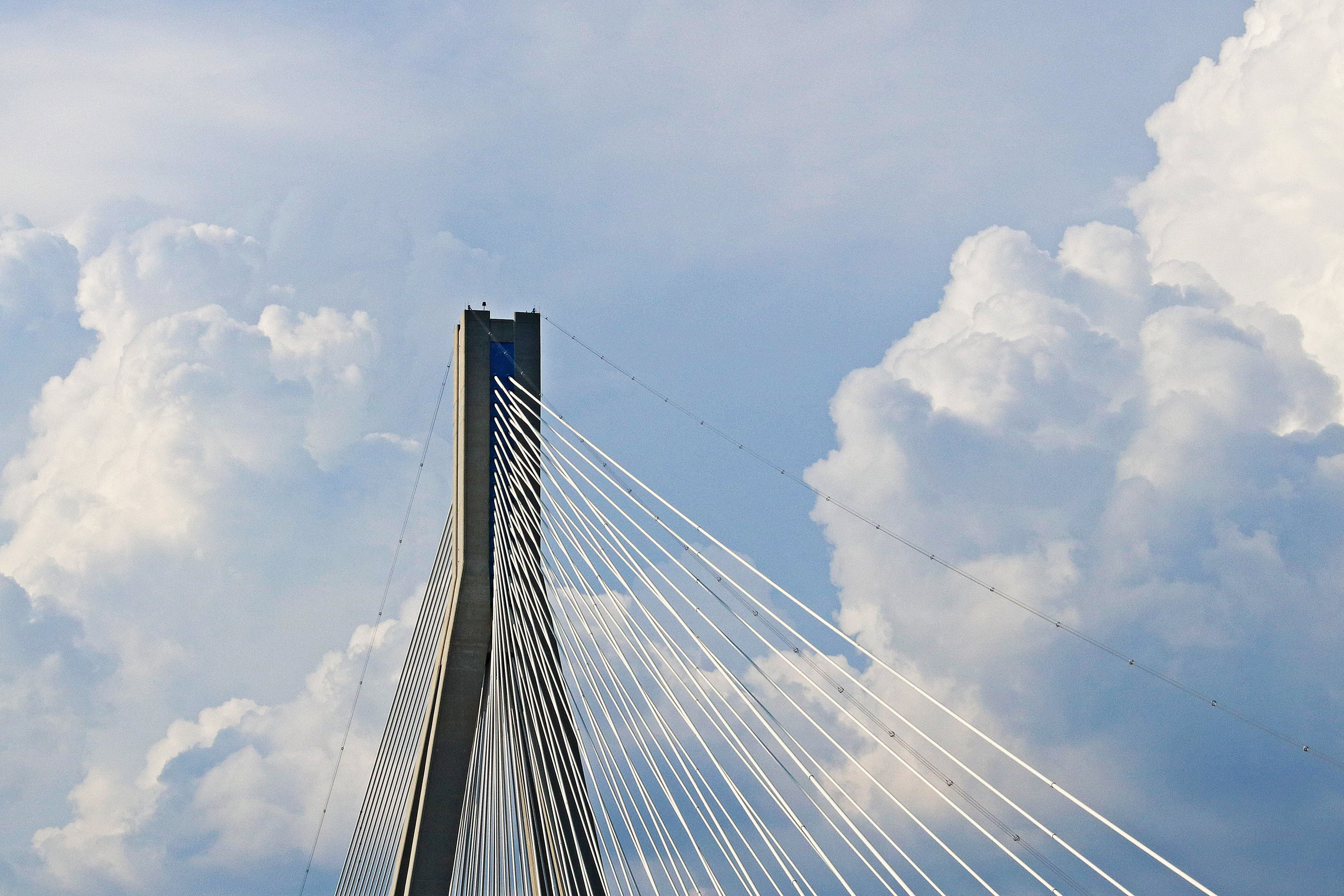
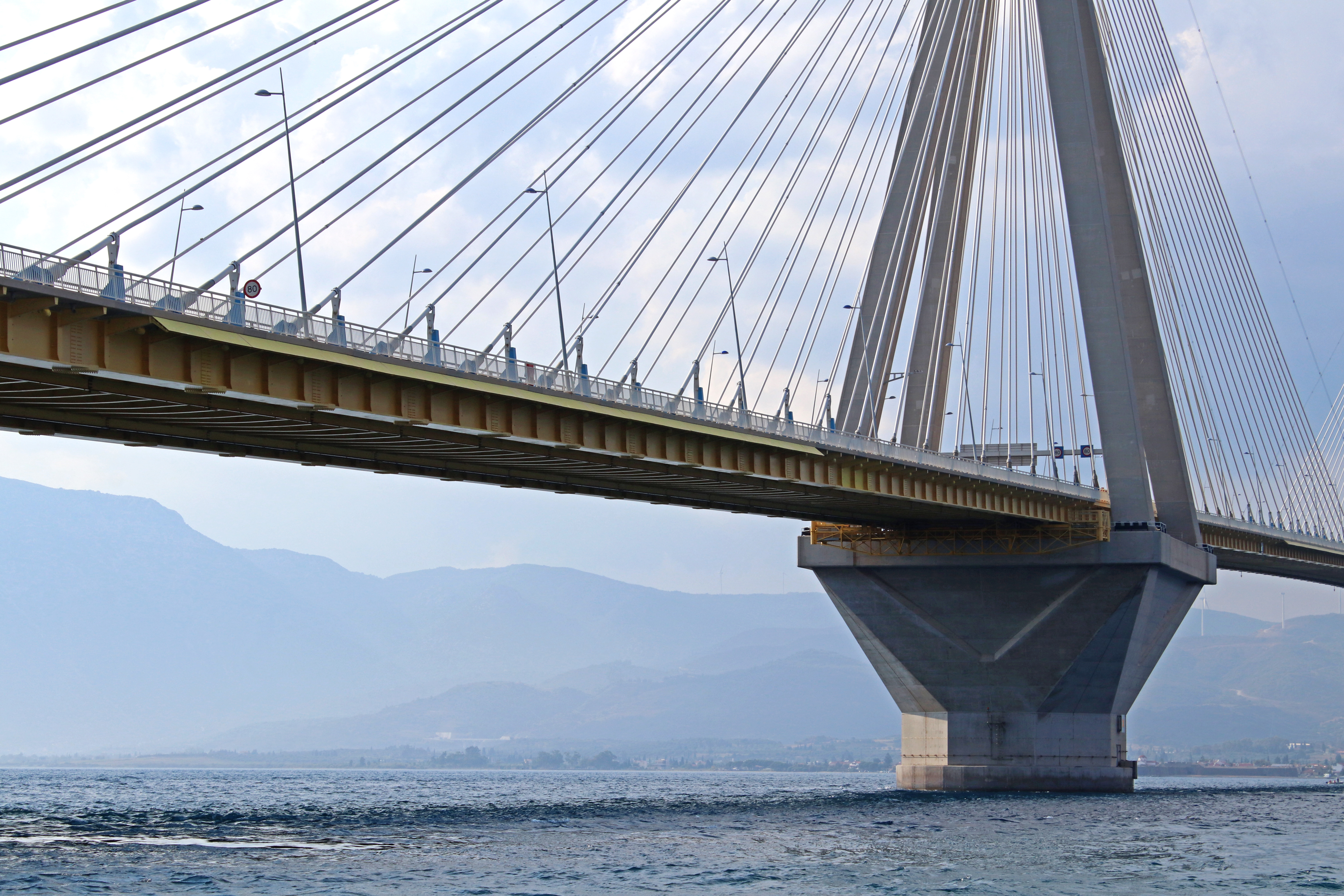
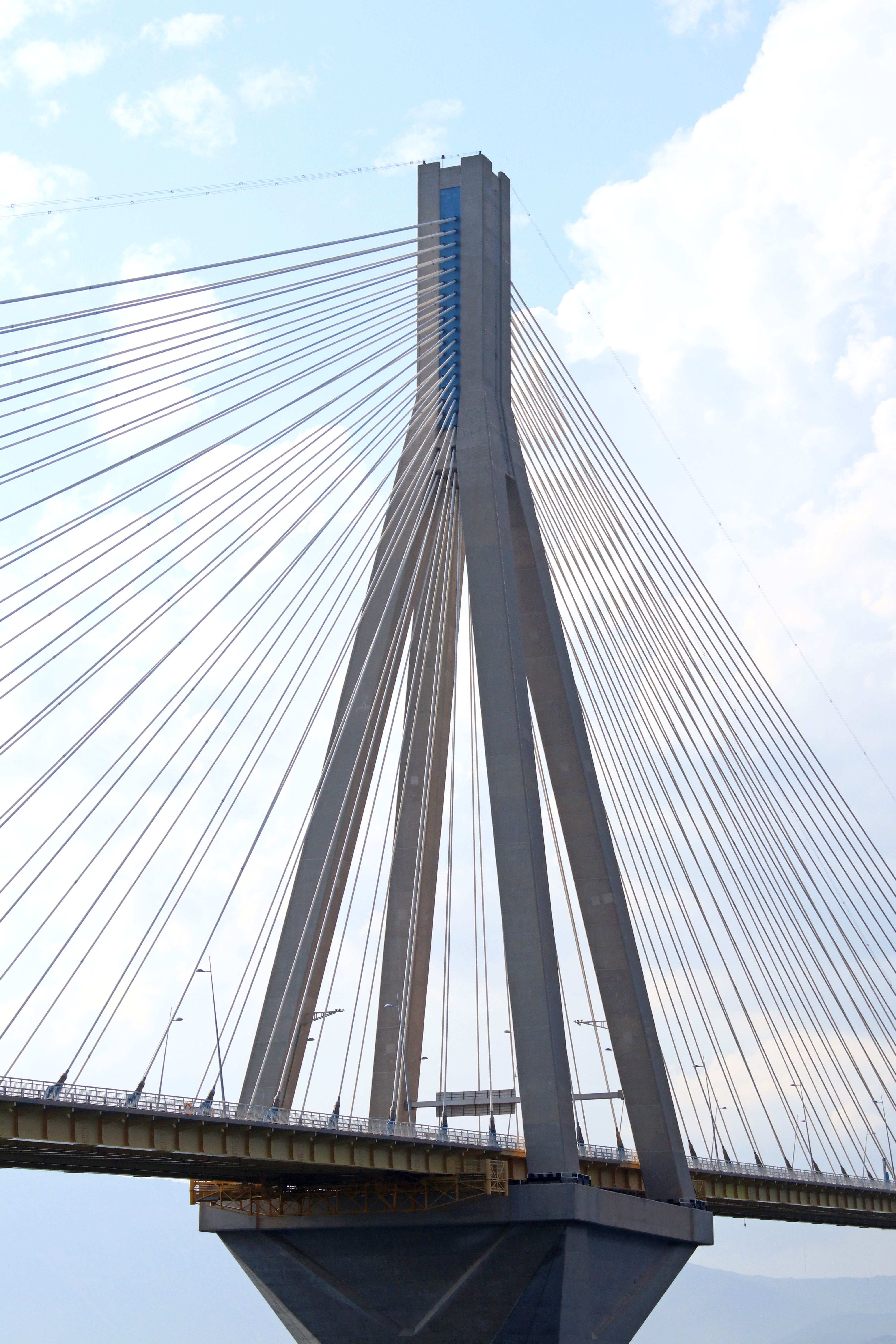
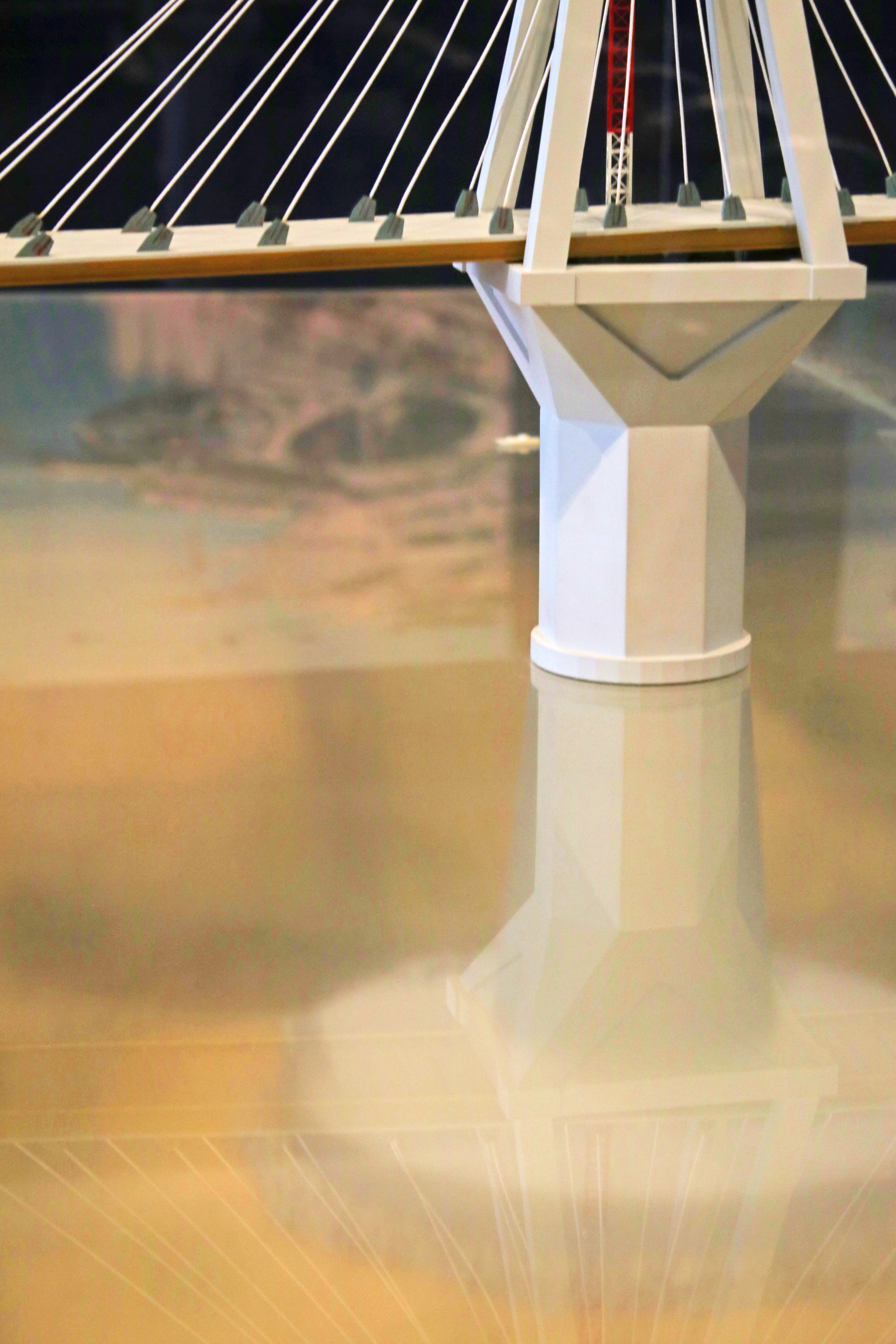
- Vertical development of the pylons: on top of the gravel layer that is on top of the inclusions, the base of the pylons rests. It is a 1 m thick bottom slab plus a 9m high wall enclosing 32 hollow cells. The diameter is 90 m. Following, there is the conical shaft of the pylon, going from around 35 m diameter at the bottom to 25 m at the top, rising around 60m. That´s not all. The other part of the pylon shaft is vertical and octagonal, having a height of around 28 m. It supports a 16 m high pyramidal capital until a top square base 40 m wide from which 4 legs (4 m x 4 m) rise 78 m up until they converge to form the pylon head (steel core between concrete walls), 35 m high. Impressive dimensions. This means that, from sea bottom to pylon top, they are 230 m high.
- Cables are arranged in two inclined planes in a semi-fan configuration, with a diameter of 350 mm. There are 8 sets of 23 pairs of cables, and strands range from 43 to 73. The sheath has a helical spiral to avoid the problem of Von Karman vortices due to wind loads.
Construction process
Construction of this amazing bridge was another great engineering challenge. Sea deep levels of 65 m, huge foundations to build… Some engineering achievements are described below.
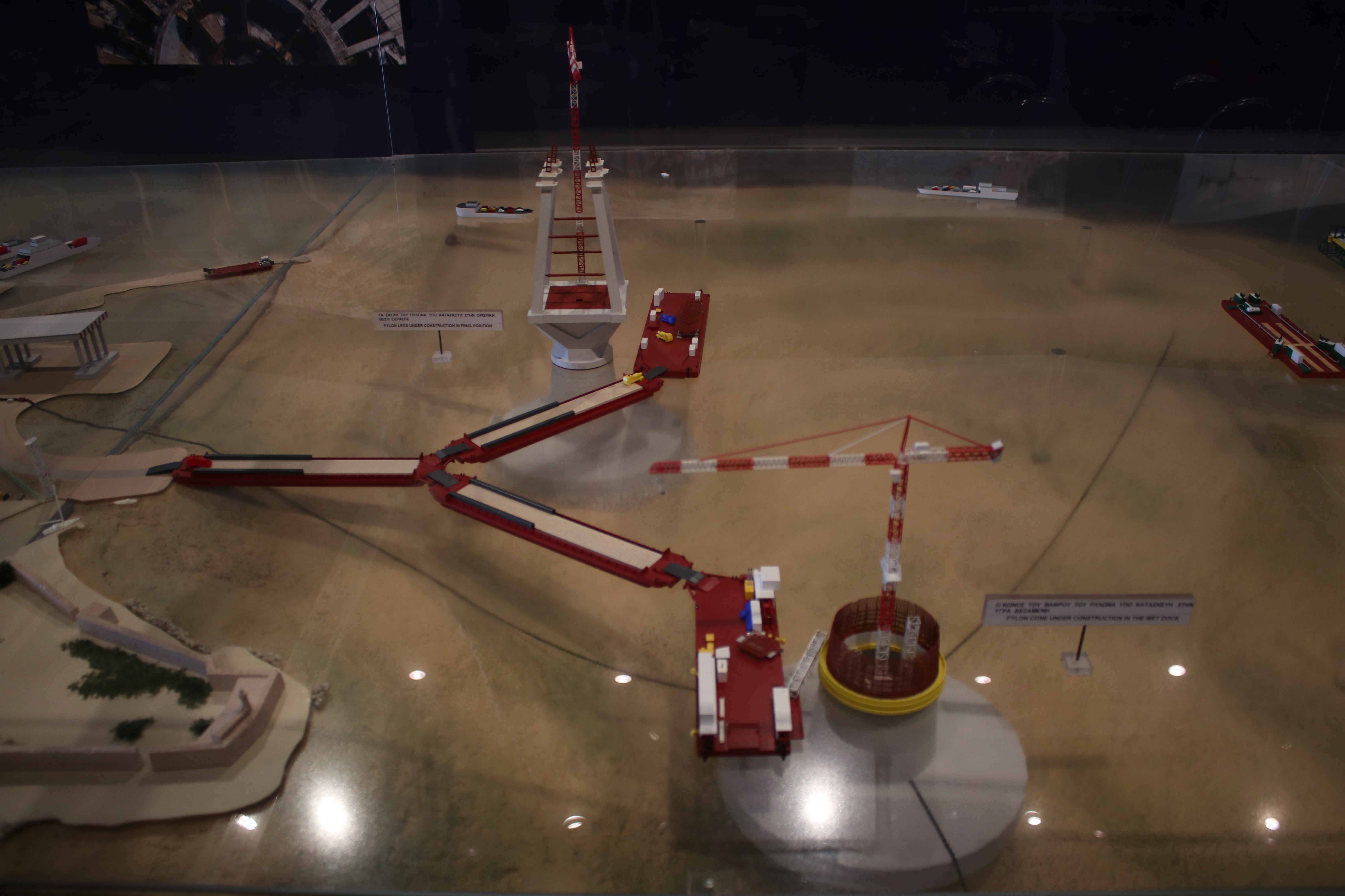
For the foundations, a dry dock 200 m long, 100 m wide and 14m deep was established near the site. Two foundations (pylon bases) could be built at the same time. The dock was closed by a sheet piled protection dyke, which was removed when the first base was ready to go out into the sea. At this moment, the second one is floated to the front to close the dyke without introducing the piles again, and be able to start the next one.
But, how do you put these bases into their place? Offshore techniques were used, following the ideas of Guy Maunsell, a British engineer who designed sea forts during the World War II, through a procedure based on constructing the structure on a dry dock and then floating and sinking it:
- Foundation is built in a dry dock.
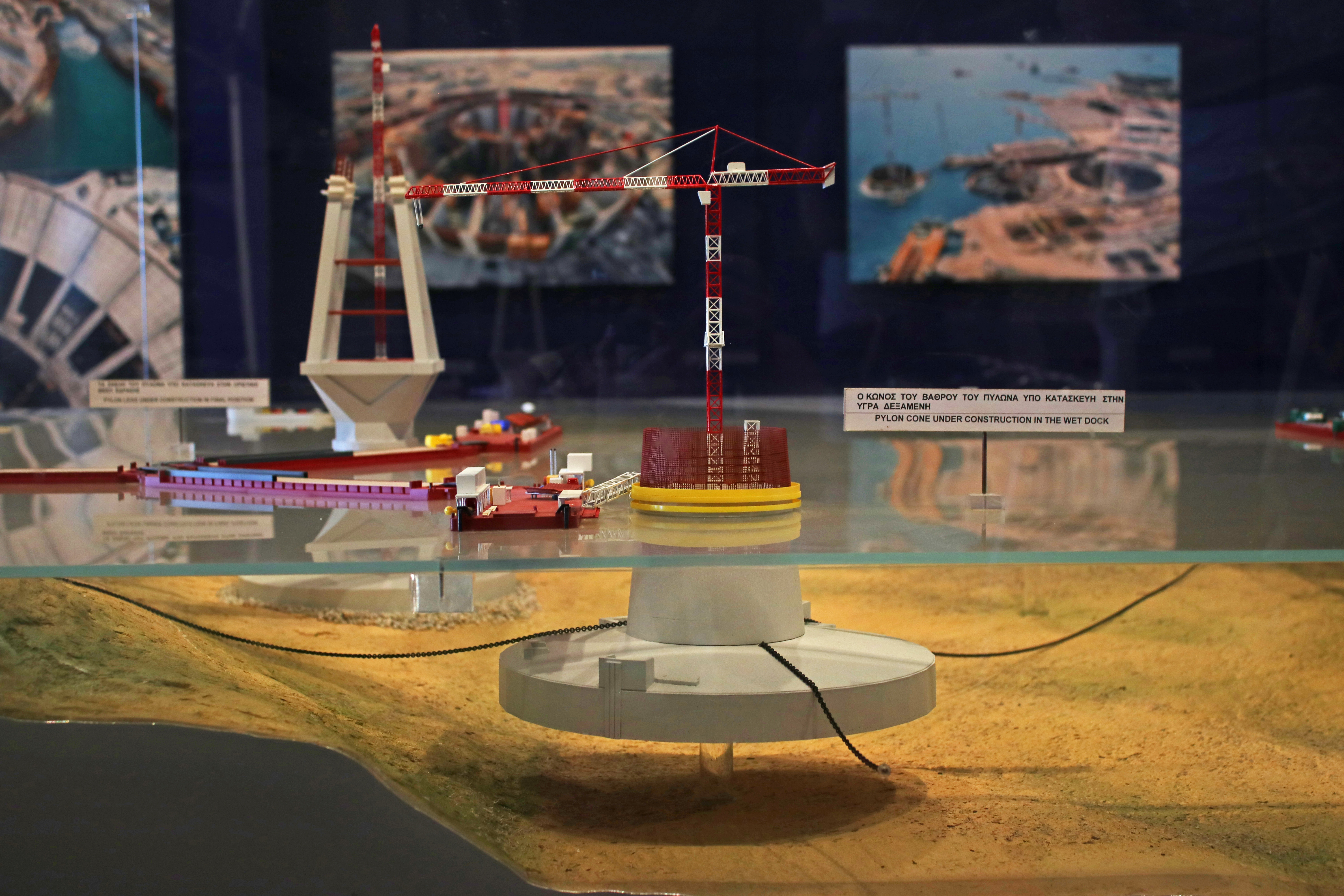
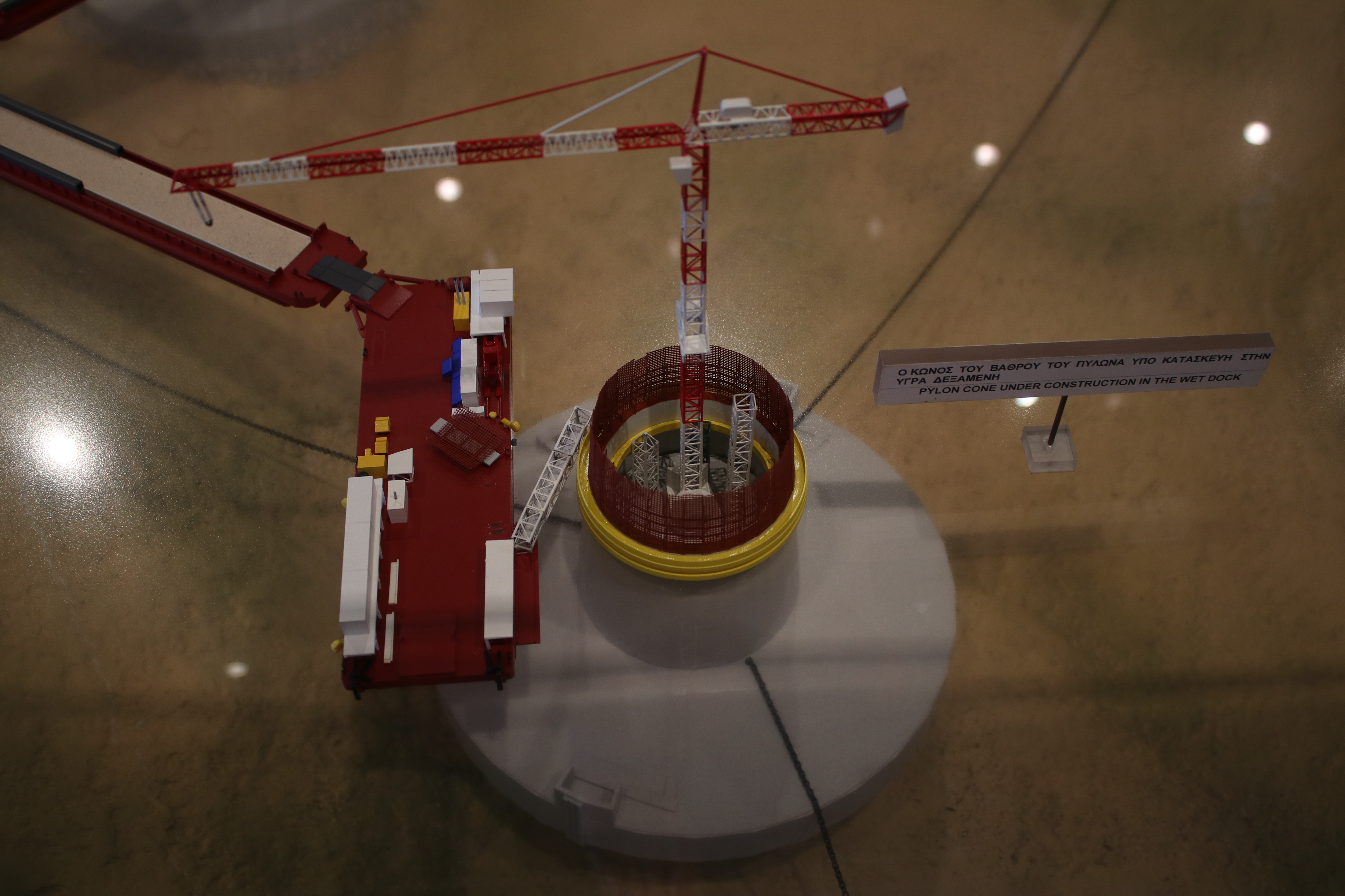
- Then, it is towed to a wet dock, and keeps there floating, anchored with chains.
- Construction of the shaft starts, with self-climbing formworks. They start sinking as more weight is being added. Also, cells in the base are progressively flooded to control and maintain a constant height above water.
- Finally, when the first part of the shaft is completed, they are tugged and sunk to their final position.
In order to accelerate settlements (20-30 cm total), so they don’t affect that much to the superstructure, there was a pre-loading by filling part of the pier with water, to a total weight slightly larger than the final pier weight. As construction progressed, water was taken out.
Before all of this, preparing the seabed, with the inclusions and the gravel layer, was made with the use of a custom-made tension-leg barge which carried the equipment and support some submersible pontoons necessary to execute the works. The idea is that dead weights lying on the seabed are connected to the barge by tension chains. About five months were necessary to prepare the sea bed under each pylon base.
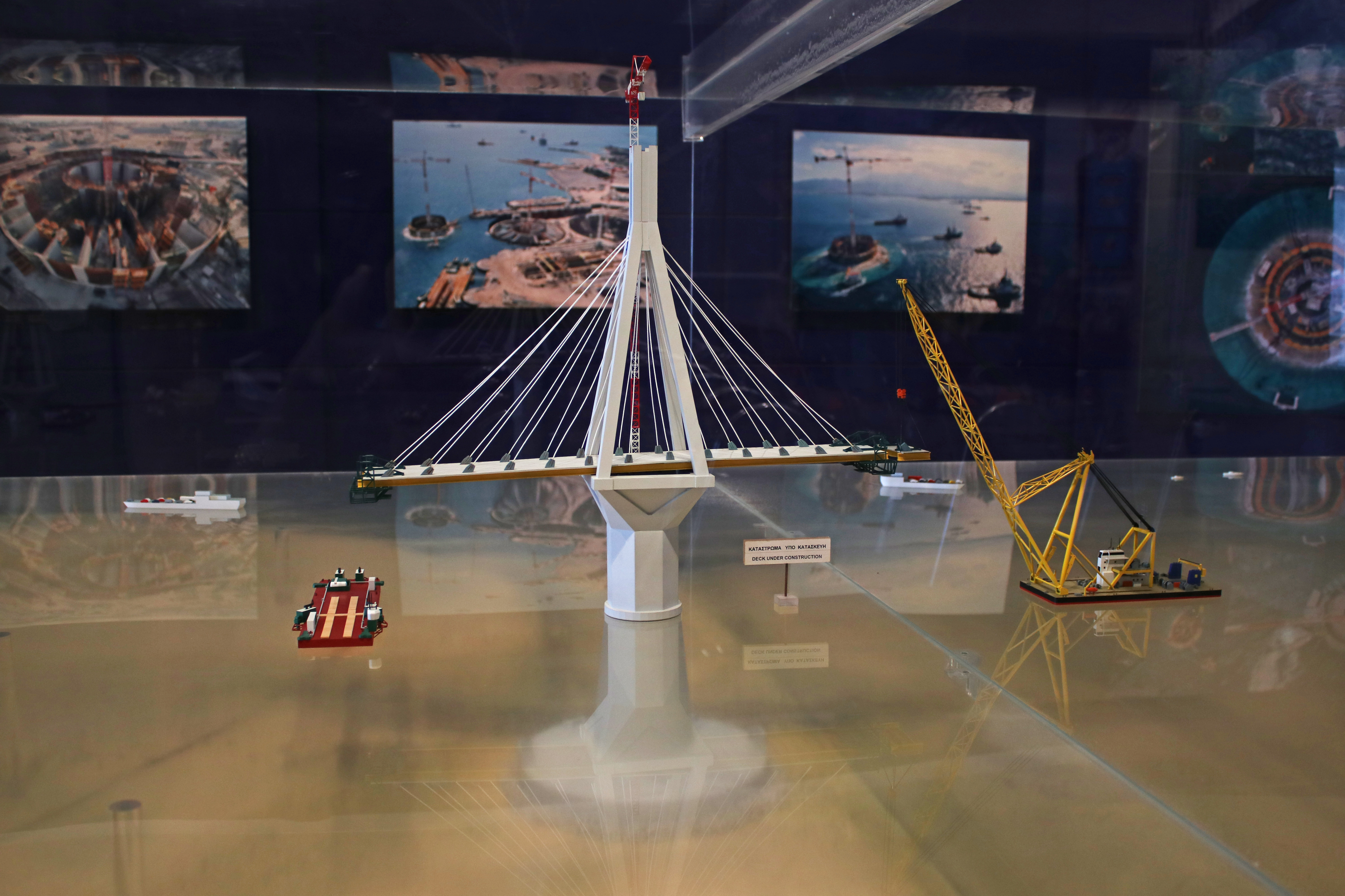
Classical balanced cantilever erection method was used for placing the deck and its erection took 13 months.
Visit it!
As a very great thing, the bridge has an Exhibition Center where you can take information and learn about the bridge and its construction.
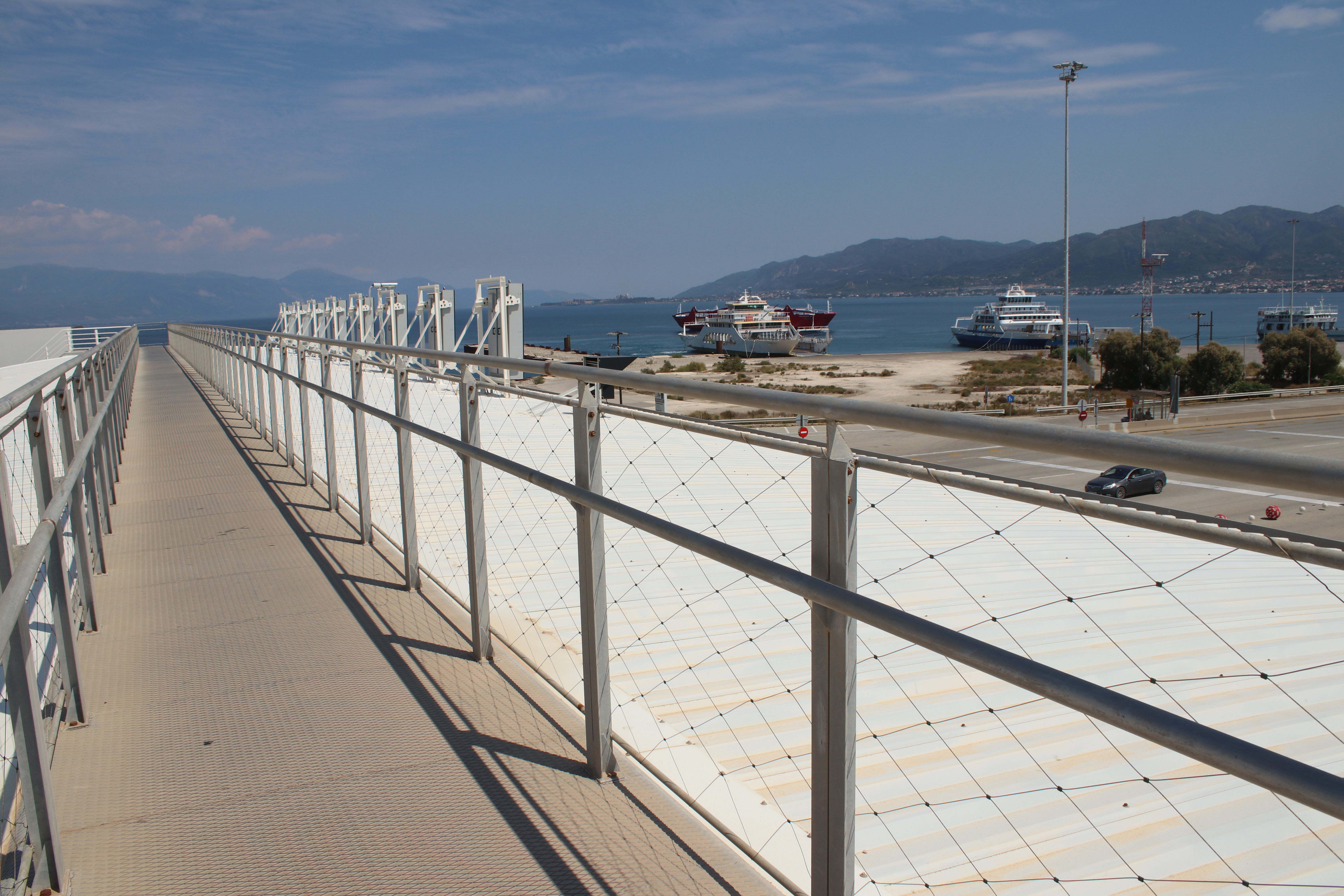
Coming from Rion, leave the car in a parking area on your right, just before crossing the Toll Plaza on the other side. Next to it you’ll find the Bridge administration building which houses its Exhibition Center. Coming from Antirion, you can park at your right, and then use the footbridge and pass over the Toll Plaza in order to reach the Center on the opposite side.
What can you expect? A big model showing the bridge under construction, photographs with explanations, some videos from the preliminary works period, the construction period and the celebrations for the bridge inauguration, even a gift shop!
A place to put in value a very special structure, and engineering as part of it, linking two coasts since August 8th, 2004, when Charilaos Trikoupis Bridge was inaugurated.