Introduction
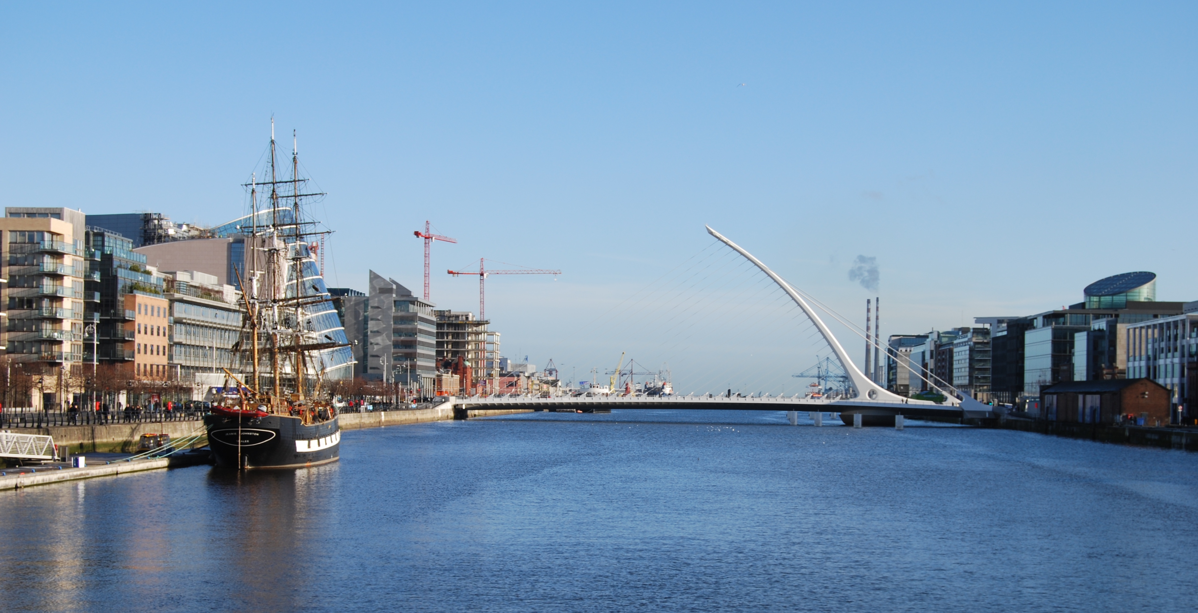
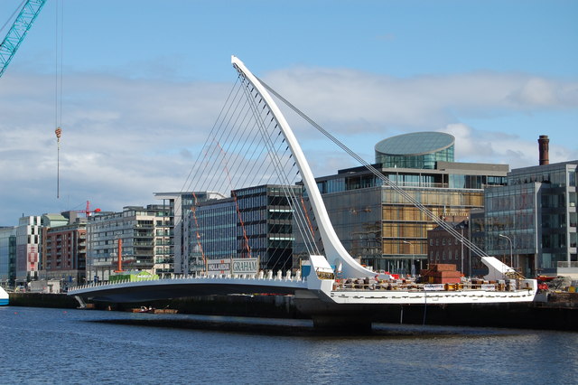
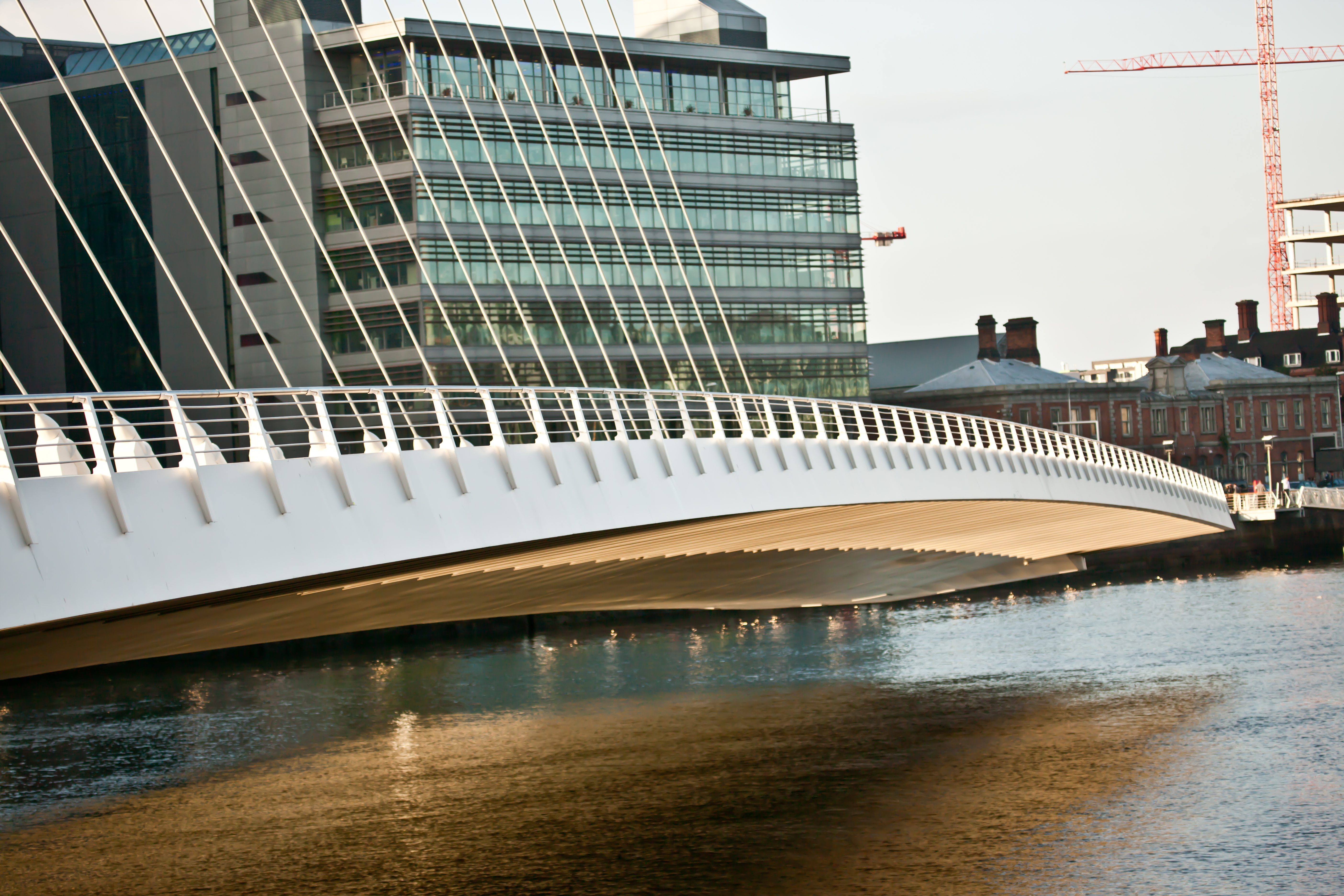
The Samuel Beckett Bridge is one of the many bridges that crosses over the River Liffey in Dublin, Ireland. It joins Sir John Rogerson’s Quay on the south side to Guild Street and North Wall Quay in the Docklands area. The bridge was named after Samuel Beckett, Nobel Laureate, to complement the sister bridge, James Joyce, located up stream.
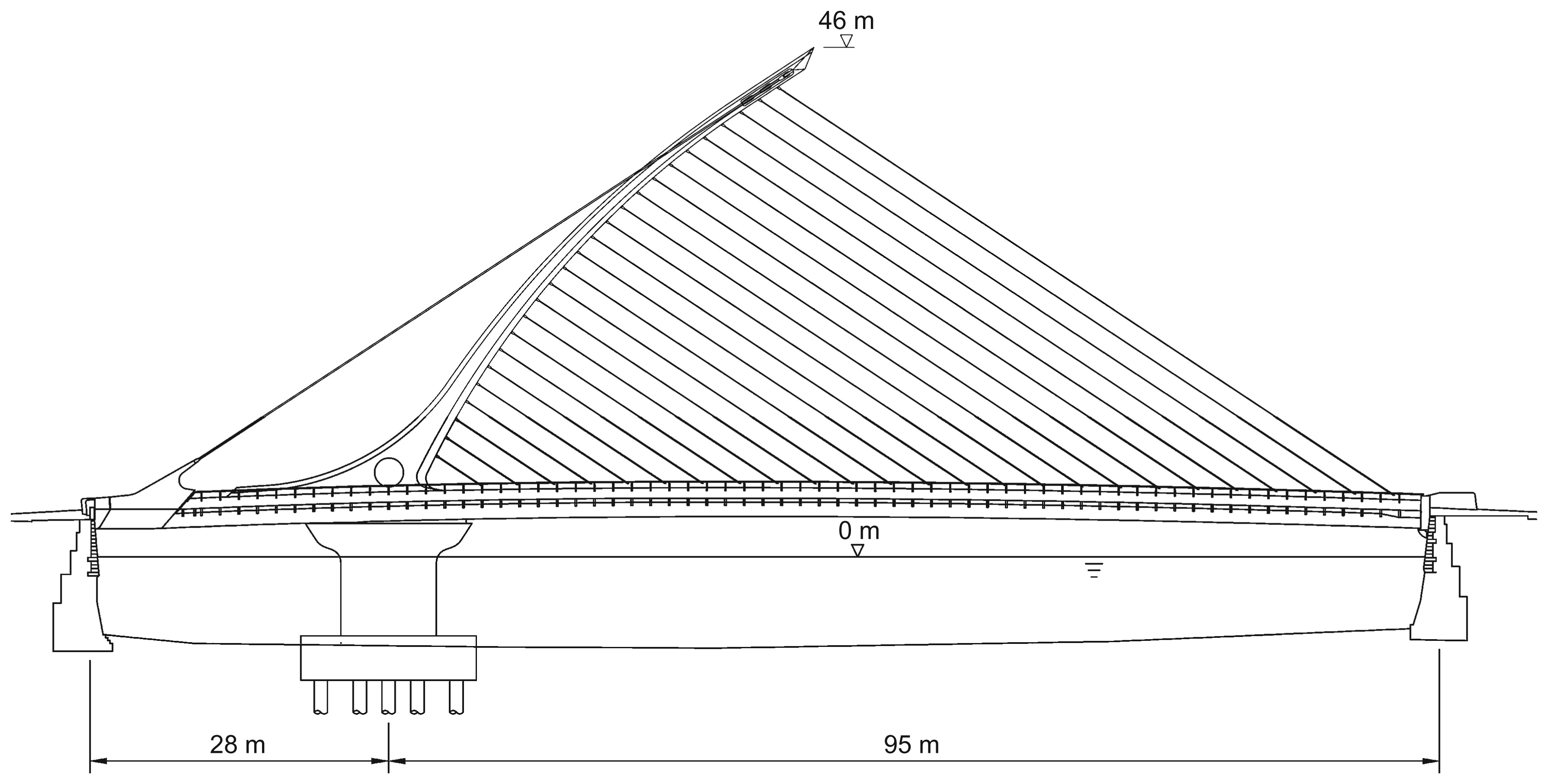
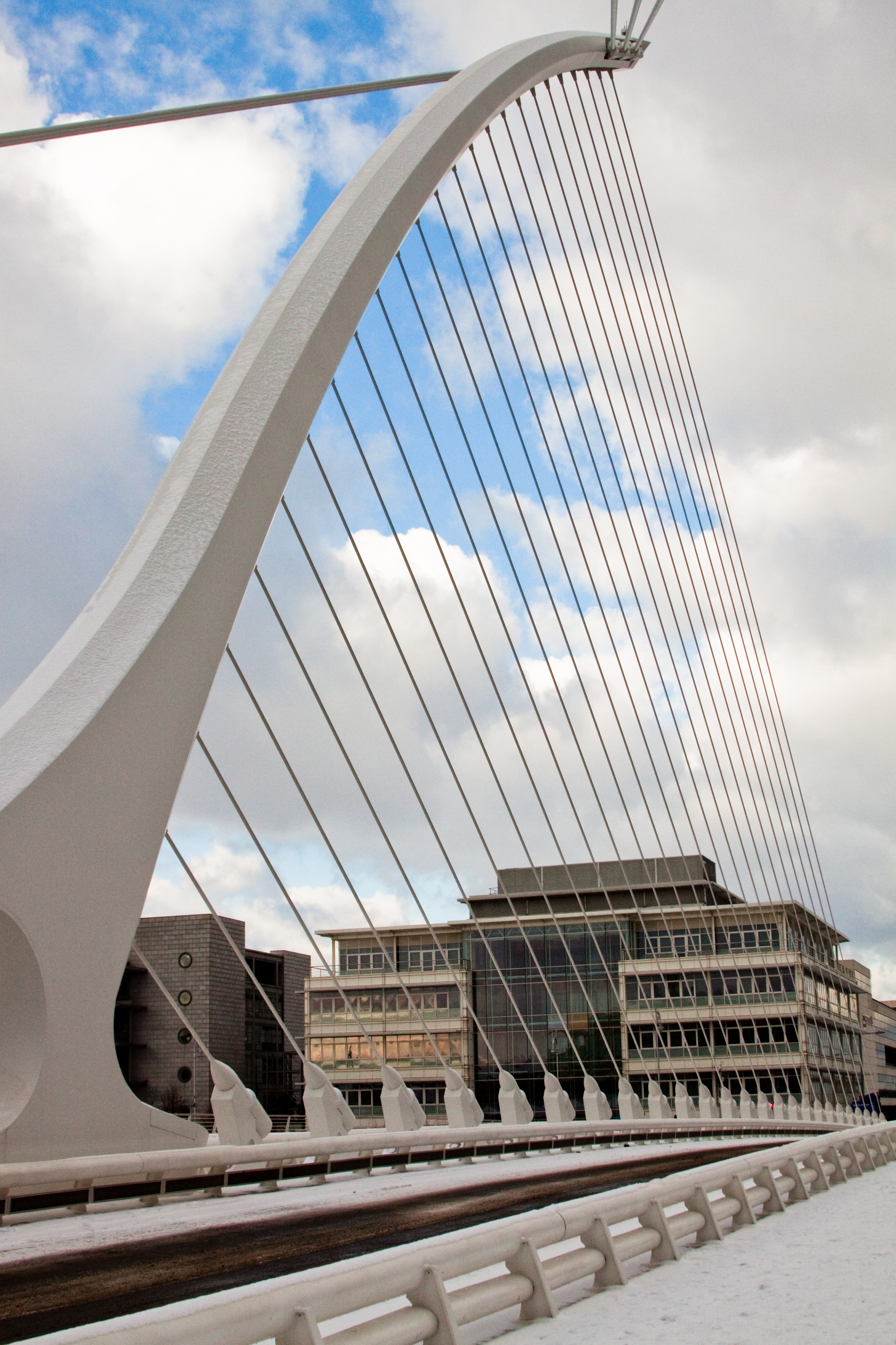
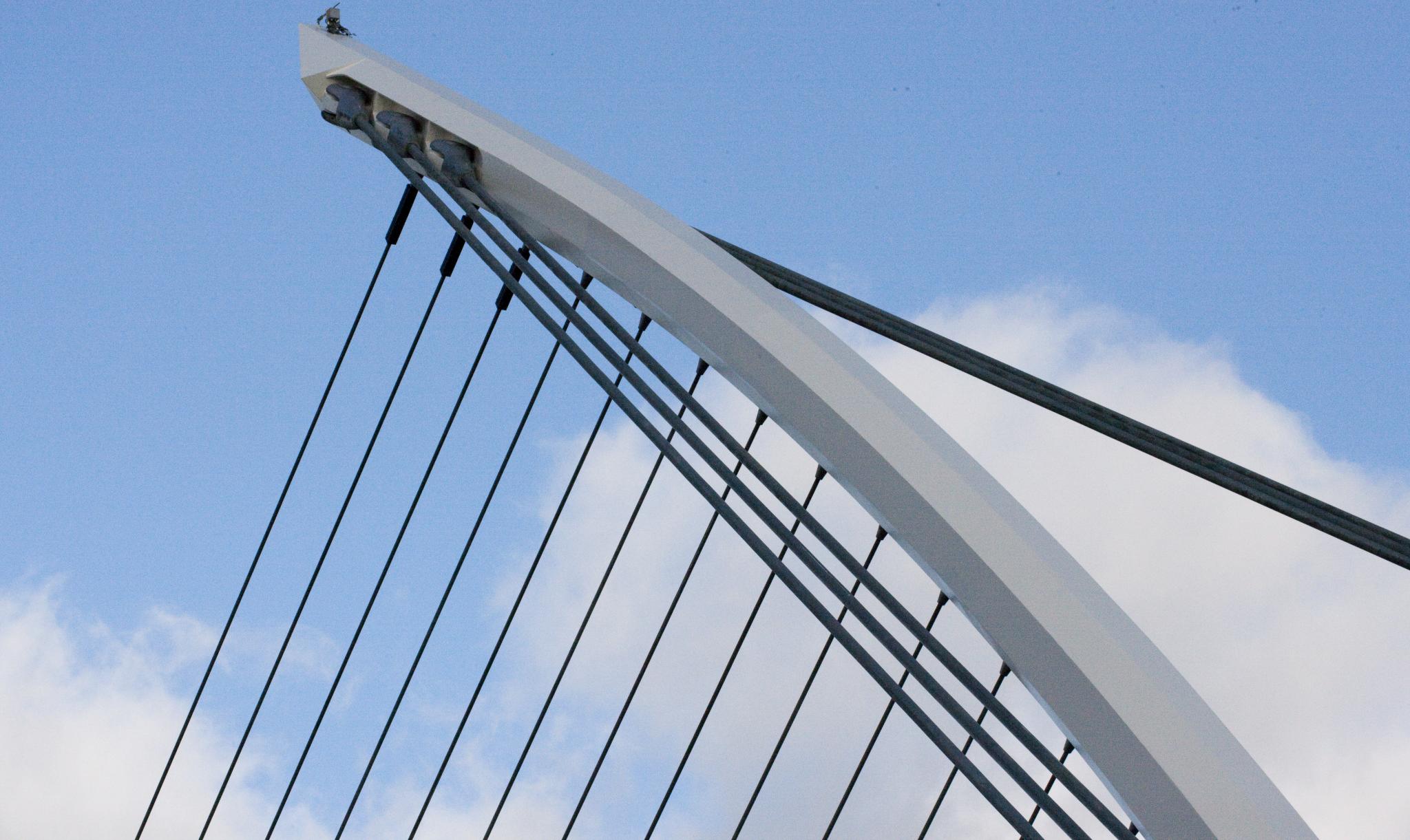
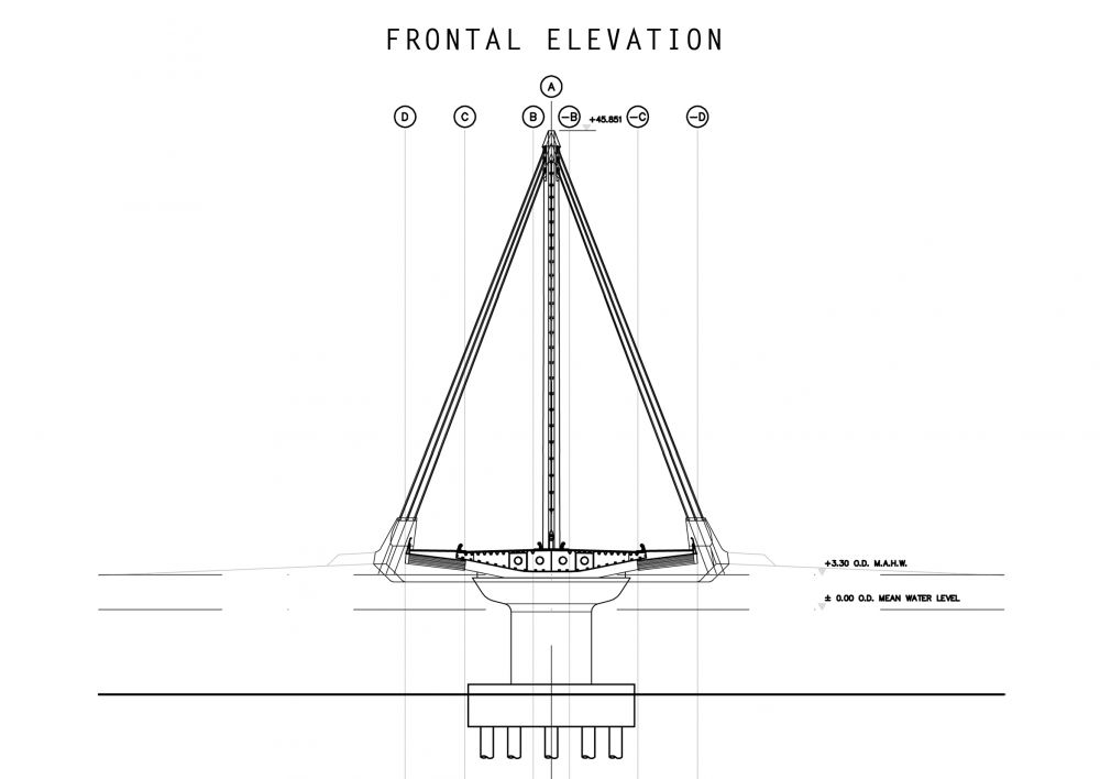
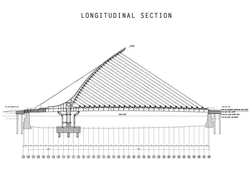
It is an asymmetric cable-stayed bridge with a length of 123 m and a span of 95 m, having two pedestrian and cycle tracks, two traffic lanes and two lanes dedicated to buses. It may be adapted to accommodate trams in the future. The designer, Santiago Calatrava Arquitects & Engineers, together with the local engineering firm Roughan & O’Donovan, made the shape of the pylon and its cables as to evoke the image of the national symbol of Ireland: the harp.

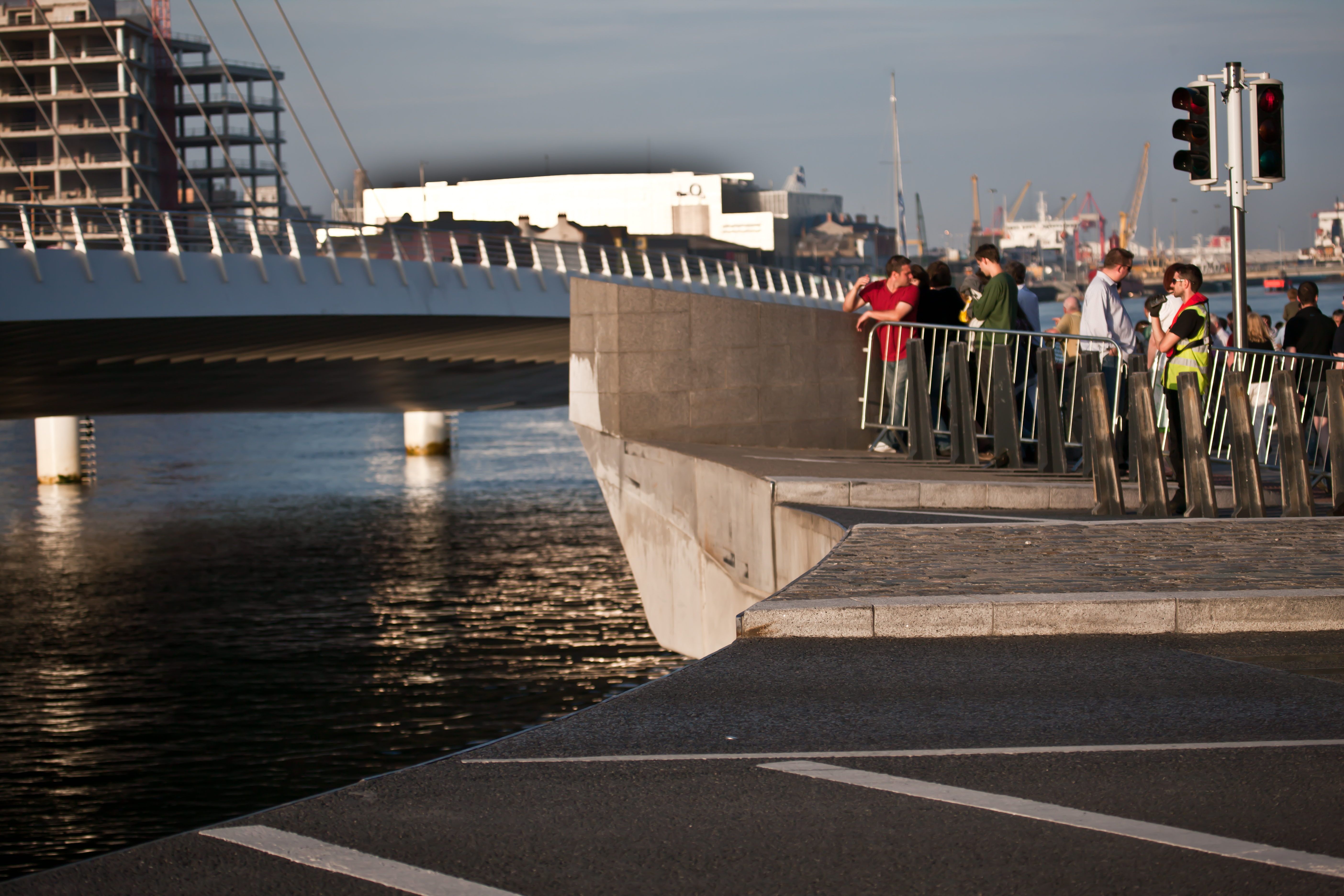
Also, the bridge opens by rotating 90 degrees over its pier, as the Dublin Docklands Master Plan from 1997 required that all future bridges within the area have this characteristic in order to facilitate the shipping movement.
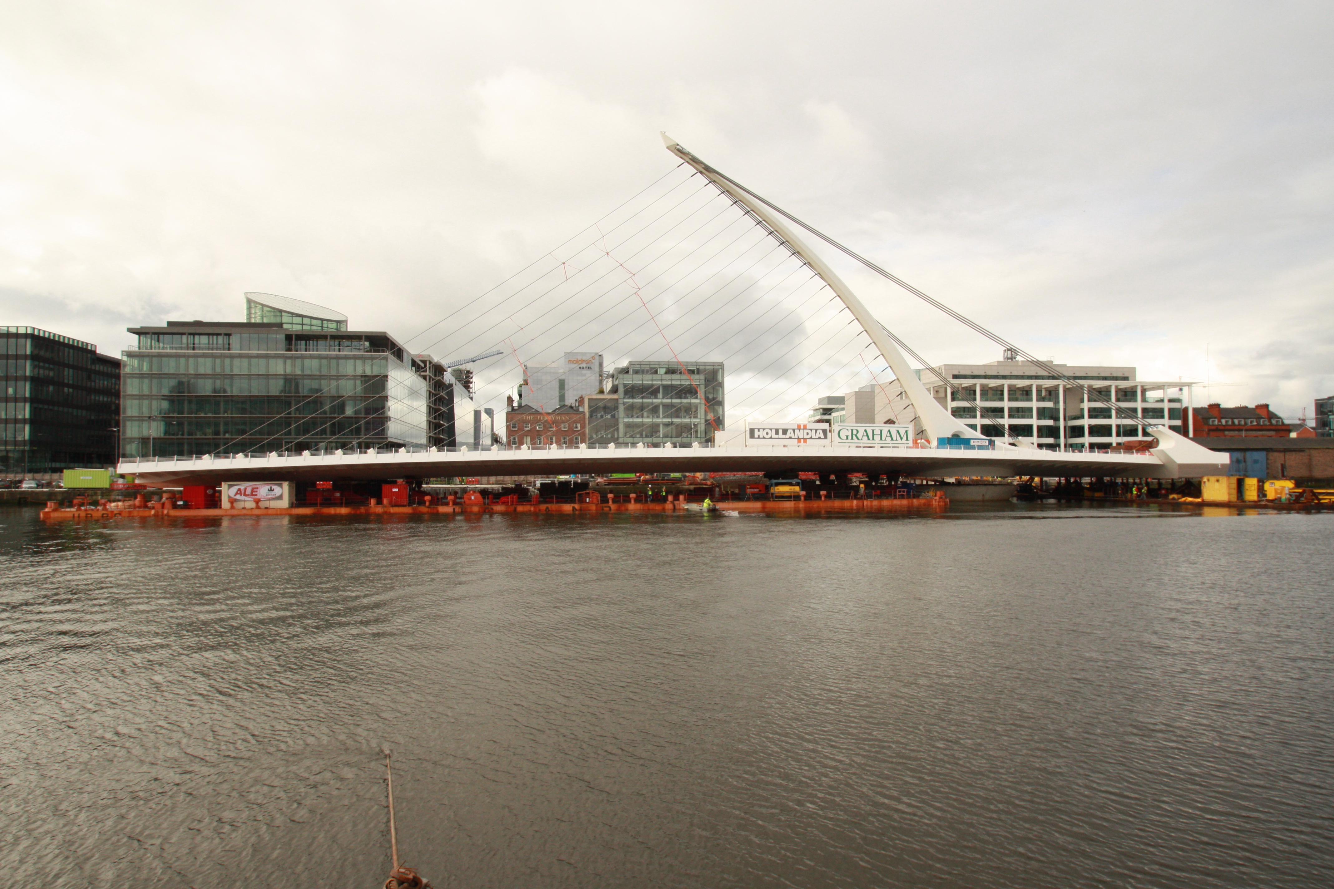
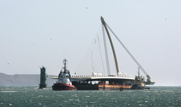
The steel structure of the bridge was constructed in Rotterdam and then transported to its final location in Dublin. Let’s discover this engineering masterpiece.
Geometry
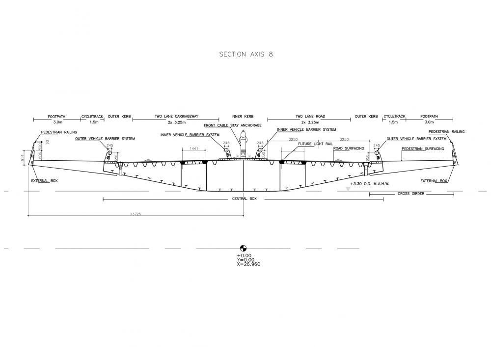
Cross section of the deck
The width of the bridge is around 27 m, and it has two pedestrian and cycle tracks plus four lanes for vehicles. Two of these lanes can be adapted to accommodate trams in the future.
It is a steel multi-cell box girder from which the ribs and steel decking forming the pedestrian and cycle tracks cantilever. The top plate of the box is only 14 mm thick, but it has 12 mm trapezoidal stiffeners every 0.5 m. The back span houses the counterbalance (concrete and steel) and the plates are not stiffened.
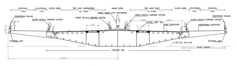
It has a 36 mm mastic asphalt layer and there are expansion joints at both ends of the bridge.
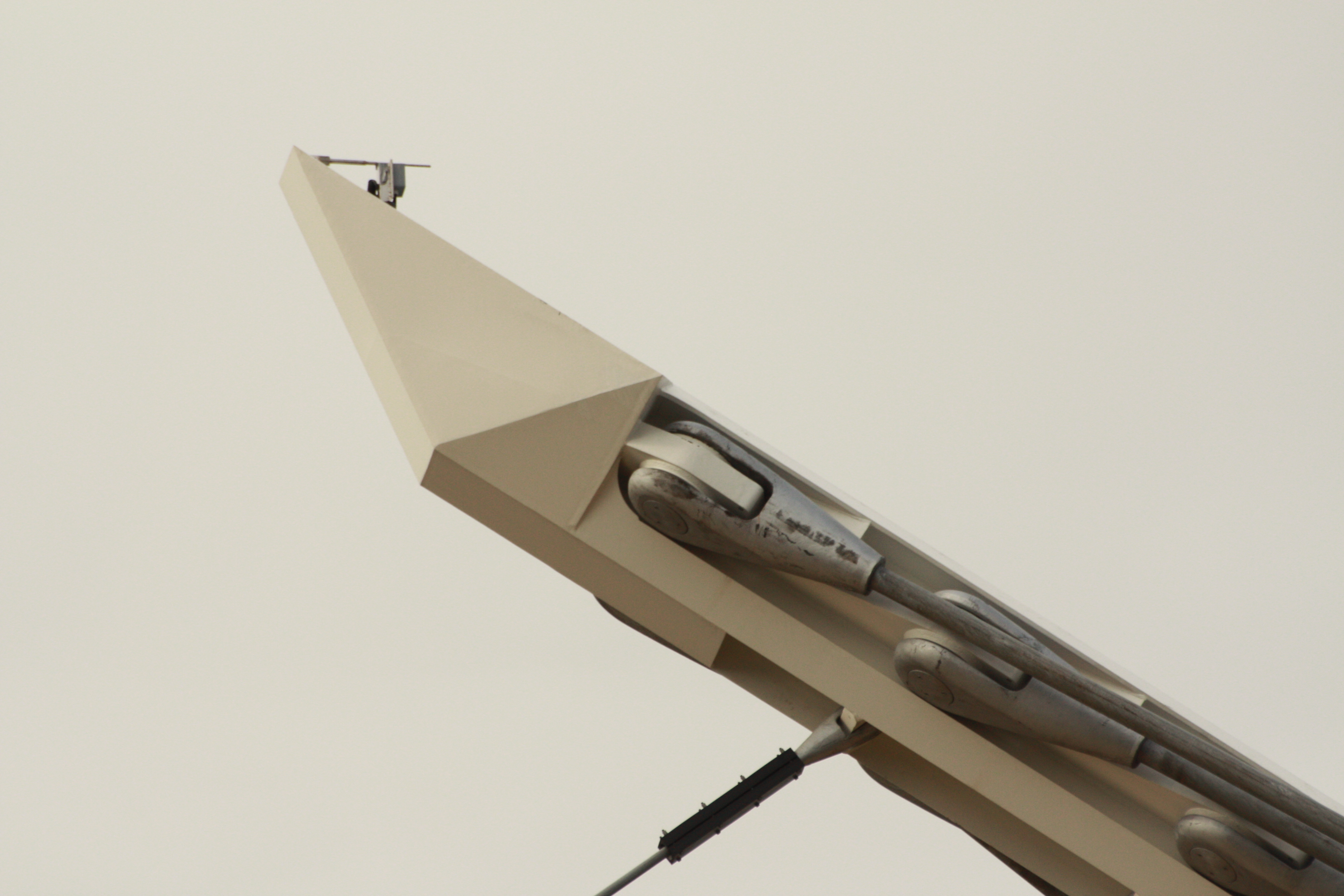
Cables
The cable-stays are locked coil cables, that is, they are formed by strands arranged in concentric layers about a central one.
The front span is supported by 25 cables of 60 mm in diameter set in a ‘harp’ formation.
There are 6 stronger cables in the back with a diameter of 145 mm.
Pylon and foundation
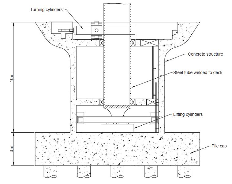
Supporting concrete pier under the deck and foundation [1]
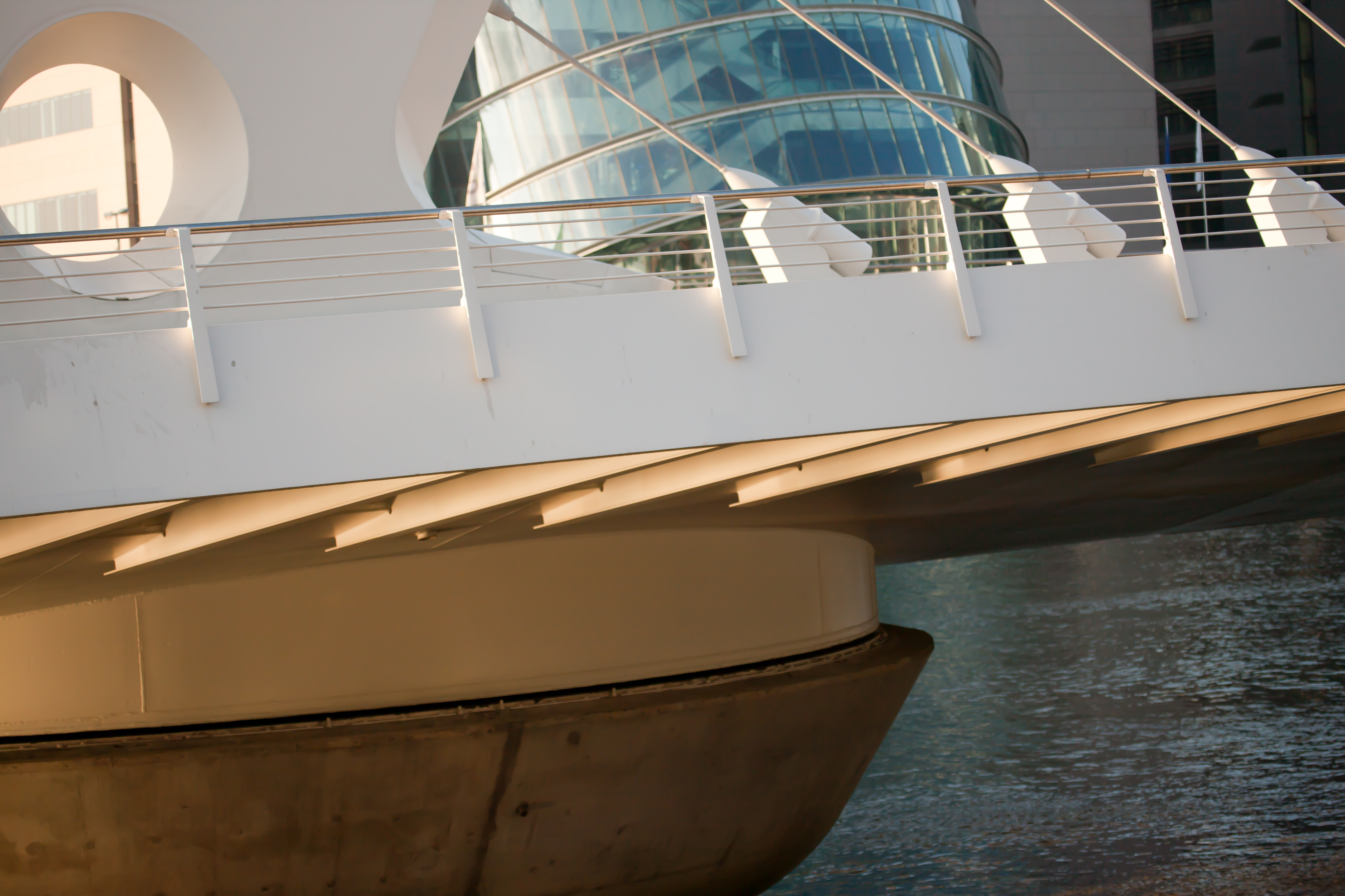
Its support consists of a circular concrete pier of varying diameter sitting on a foundation made out of bored concrete piles and a concrete pile cap.
The concrete pier has an outer diameter of 8,6 m at the base and 15 m at the top, with a height of 10 m. Inside, there is a 10 m long central steel tube with a diameter of 2,5 m and a plate thickness of 120 mm, which is welded to the deck below the base of the pylon, to transfer the load to the pile cap below.
There is a main vertical bearing at the bottom of the cylinder that transfers the vertical load to the lifting cylinders (that allow the elevation of the deck to rotate) and from there to the pile cap, while the moments are taken by two horizontal bearings encircling the central steel tube 5,35 m apart on the top of the pier.
The pile cap below the main support is a heavily reinforced concrete prism of 15x15x3 m. It is supported by 18 1,2 m diameter bored cast-in-place piles. The underside of the pile cap is approximately 13 m below high water level.
Concept
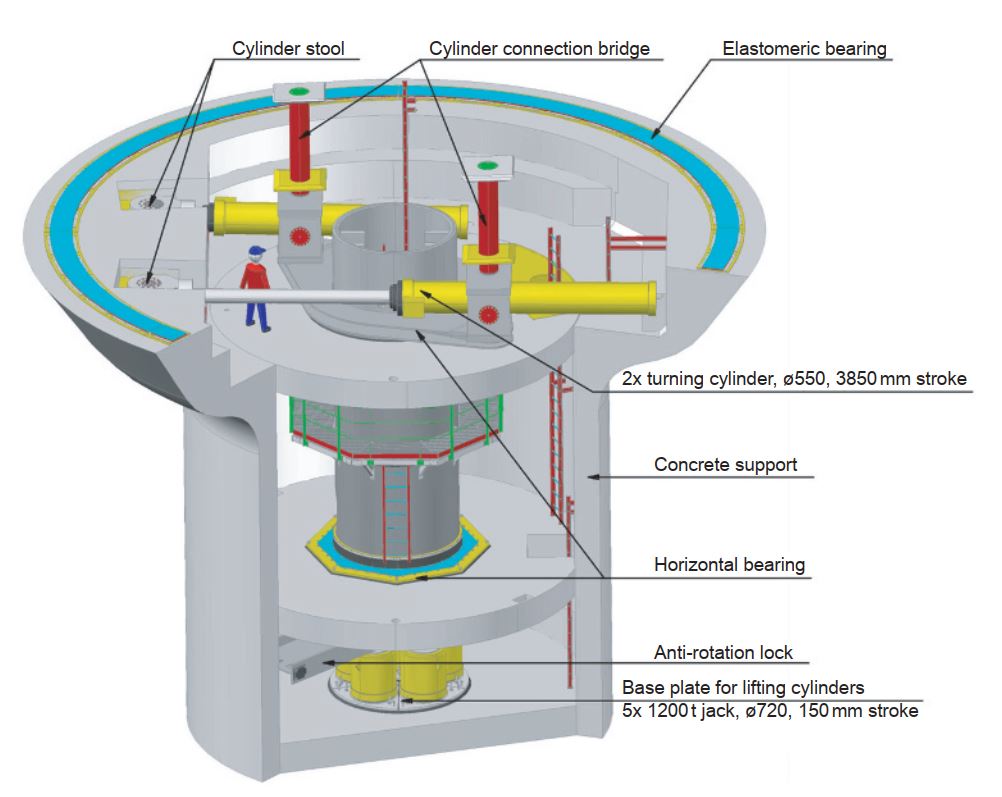
Rotation system [1]
When the bridge is closed, it sits on a continuous horizontal elastomeric bearing ring on the rim of the support pier, and it is kept into position by two pairs of locking pins at each end, that are inserted into housings cast into the abutments.
The expansion joints at each end of the bridge are formed by movable steel boxes, which are controlled by hydraulic rams, so that pressure can be released or increased, allowing the bridge to expand, contract, and be free to open.
The electrical control cabinets, hydraulic tanks and electrical pump units are all located within the bridge deck structure close to the base of the pylon.
Structural design
This special bridge was designed for two different situations, as it has to resist live loads (traffic and pedestrians) when closed, but it also has to bear its own weight when it’s opened and only supported on the pylon.
The worst case of analysis is the opened situation, where forces and deflection of pylon and deck had to be minimized by designing the counterbalance in the back span, mass of the elements and forces in the cables.
Structural design characteristics of the different elements are:
- The total vertical load is 5850 t.
- The multi-cell box section of the deck has a big torsional rigidity that helps resisting the large torsional forces coming from unbalanced live loads on either side of the central line of cable-forestays.
- The cells in the back span were filled with a combination of steel blocks and heavyweight concrete which also prevents the top and bottom plates from buckling locally. The amount of steel ballast is adjustable, in order to balance any future changes made on the bridge.
- The stay forces have significant horizontal components along the deck, which are balanced between the ones from the forestay cables and the ones in the back, and are resisted by the deck acting in compression.
- Minimum breaking load of the front cables is 3590 kN and of the back span cables is 20100 kN. For serviceability limit state, a maximum working load of 53% of these breaking loads was accepted, a little bit more than usual as the predominant loads are permanent.
- The pylon has to resist both axial forces coming from the cables and also bending moments.
- The buckling of the pylon was studied: it is restrained in the longitudinal direction by its arched shape and the stays, while its slenderness in the transversal direction is retained by the inclination of the backstays.
- The main support was finally decided to be built in concrete instead of steel due to long-term maintenance benefits as well as improvements during construction (fastest and easiest execution).
- The capacity of each pile is 9500 kN.
- Ship impact protection piles were placed to protect the whole bridge in its open position, and the central pier when it is closed.
Construction process
The construction started with an installation of a 20 m square AZ46 sheet piled cofferdam, driven to the top of the bedrock (about 3 m deep in the soil), in order to build the foundation. Walers and struts were progressively installed as the cofferdam was dewatered. It was necessary to place concrete as a bottom strut before the cofferdam could be completely dewatered. Pressure relief wells were installed to avoid the excess of pressure in the rock underneath and work in safe conditions.
Installation of the foundation bored piles was performed with the piling rig placed into the base of the cofferdam in order to achieve more precision.
After that, they cast the concrete pier, using a complex formwork that was designed for the curved top part.
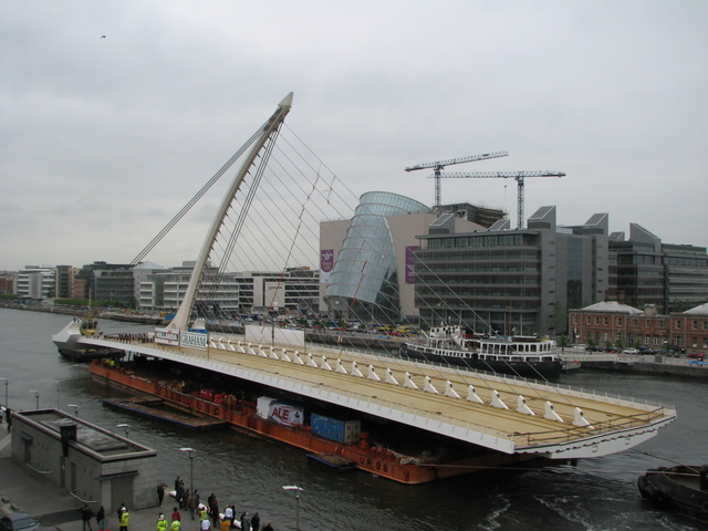
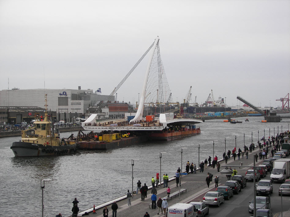
The construction of the bridge itself was the most distinctive feature. The design of the deck and the pylon was split in different sections that were made up, painted and then joined together. All these was performed in Rotterdam, so the whole bridge was later transferred onto a seagoing barge and transported to Dublin. Some railings and street furniture had to be temporarily removed from the East Link Bridge in Dublin as it was the narrowest place to cross. The Konigshaven Bridge in Rotterdam was the lowest cross.
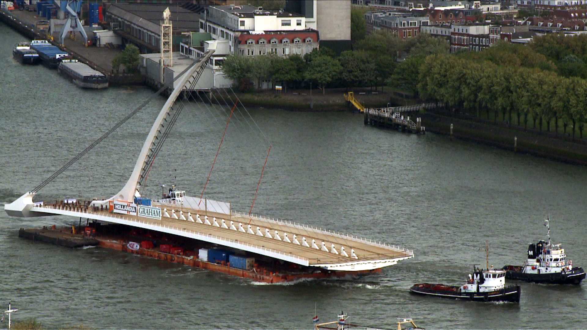
May 2009 –> 2500 tons were shipped through a 1000 km journey in 8 days.
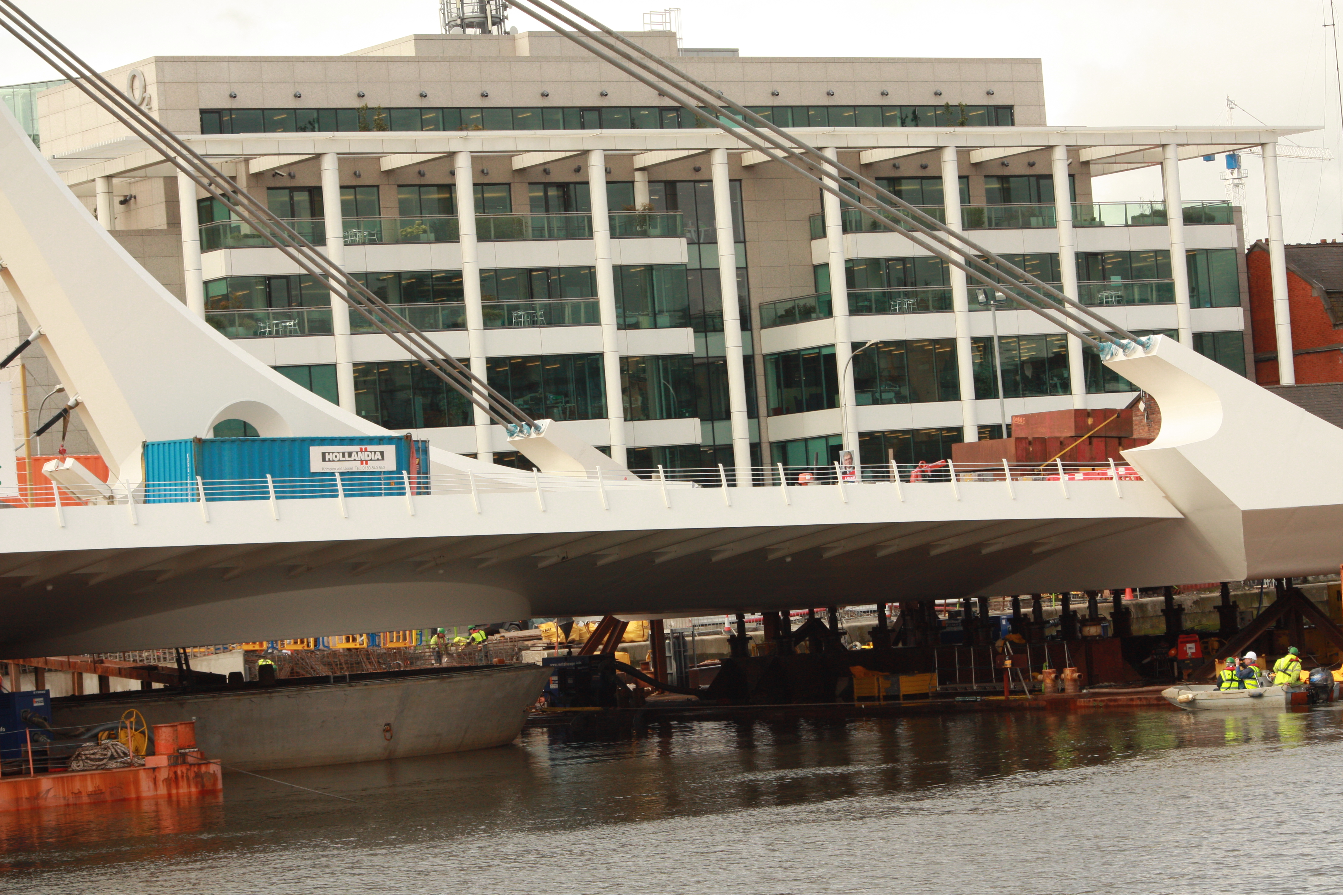
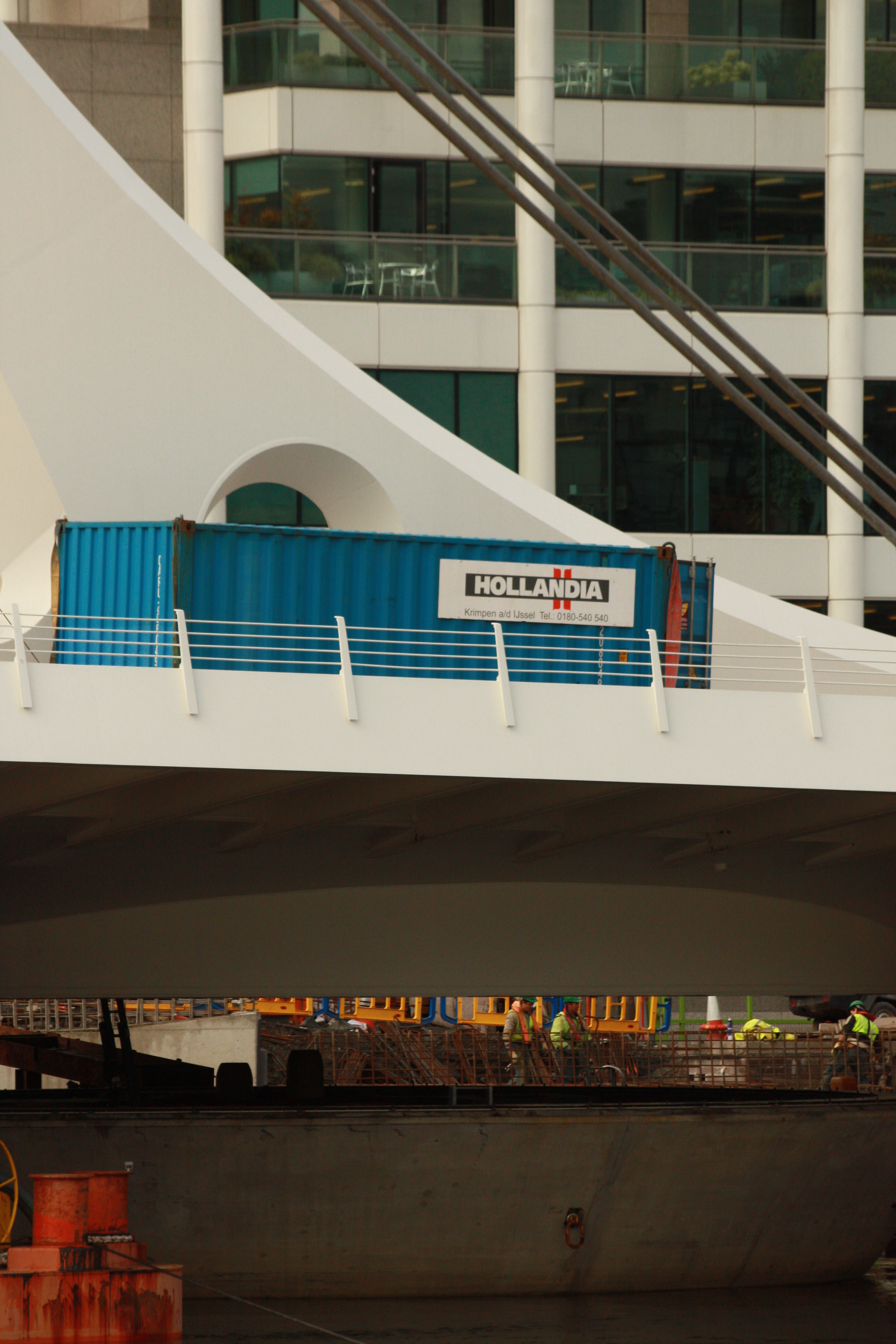
Once in Dublin, the back span of the bridge was ballast and supported on a second barge in the back, leaving the bridge support area free. At high tide, the barges were moved to place the bridge on its pier support (and the lifting cylinder). As the tide receded, the bridge lowered onto the rim support. After that, the barges could leave, and the bridge was welded to the lifting cylinder. The hydraulic system was connected to rotate the bridge 90 degrees to its closed position and cables were tensioned. Once everything was in place, abutments were finished.
Finishings such as waterproofing or asphalt were applied.
Samuel Beckett Bridge was opened by the Lord Mayor of Dublin on December 10th, 2009.
3D model
You can interact with this 3D model by Le Corb:
References
[1] https://www.icevirtuallibrary.com/doi/10.1680/bren.2011.164.3.133
[2] http://www.bridgesofdublin.ie/bridges/samuel-beckett-bridge/design-and-engineering
http://dofengineers.com/project/samuel-beckett-bridge/
Photos
Drawings

Construction pictures
-

- GUIDO BENSCHOP/AFP/Getty Images