Introduction
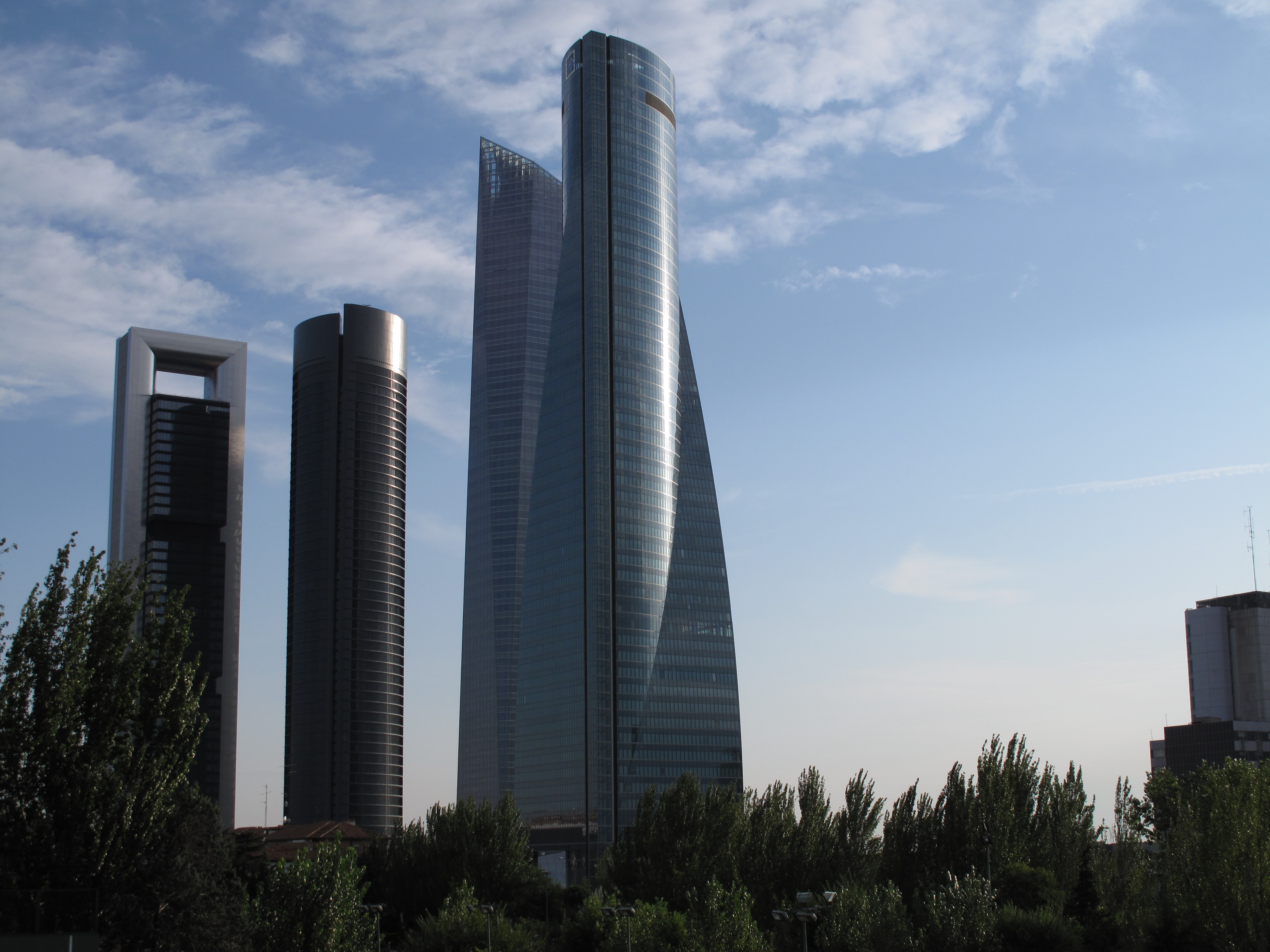
Madrid has 5 skyscrapers, and all of them are located in the northeast part of the city, the so-called financial district. The name of this area is Four Towers Business Area, being the former Real Madrid Sports City. The construction of the first 4 towers started in 2004 and they were inaugurated between the end of 2008 and the beginning of 2009.
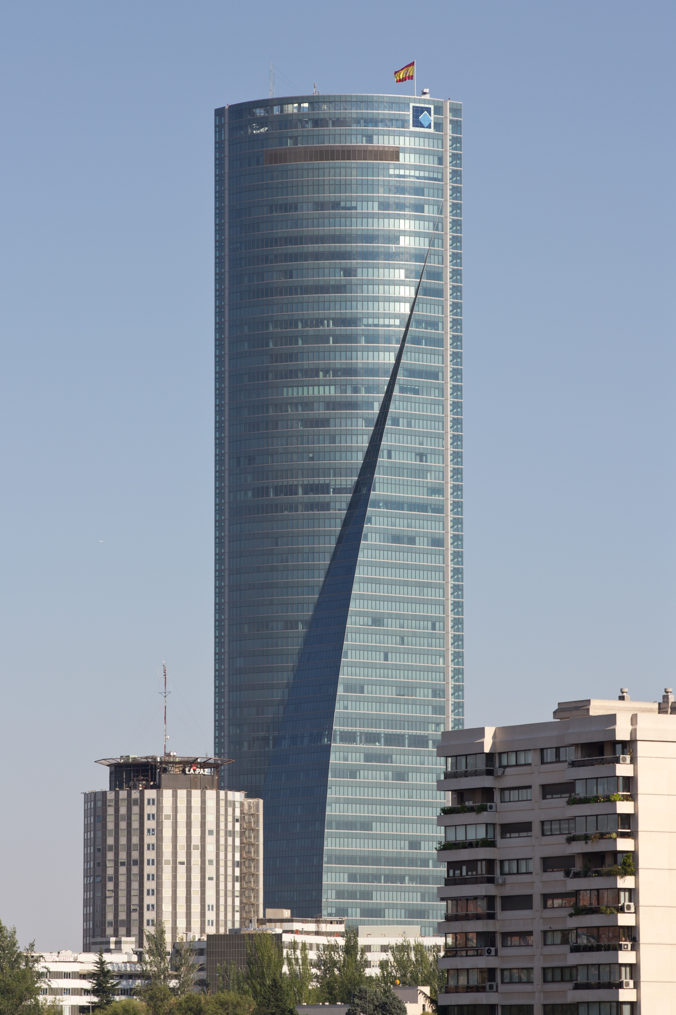
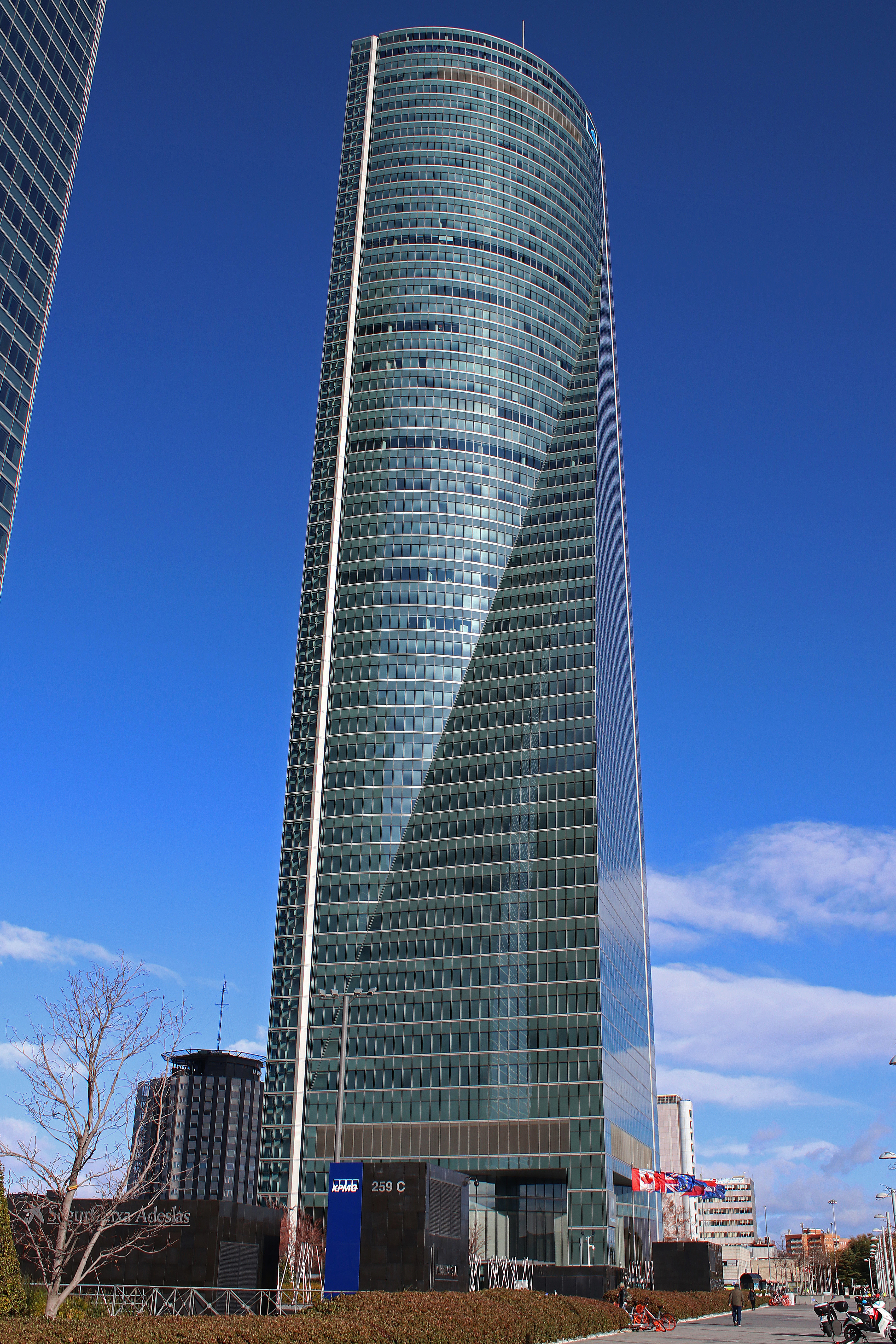
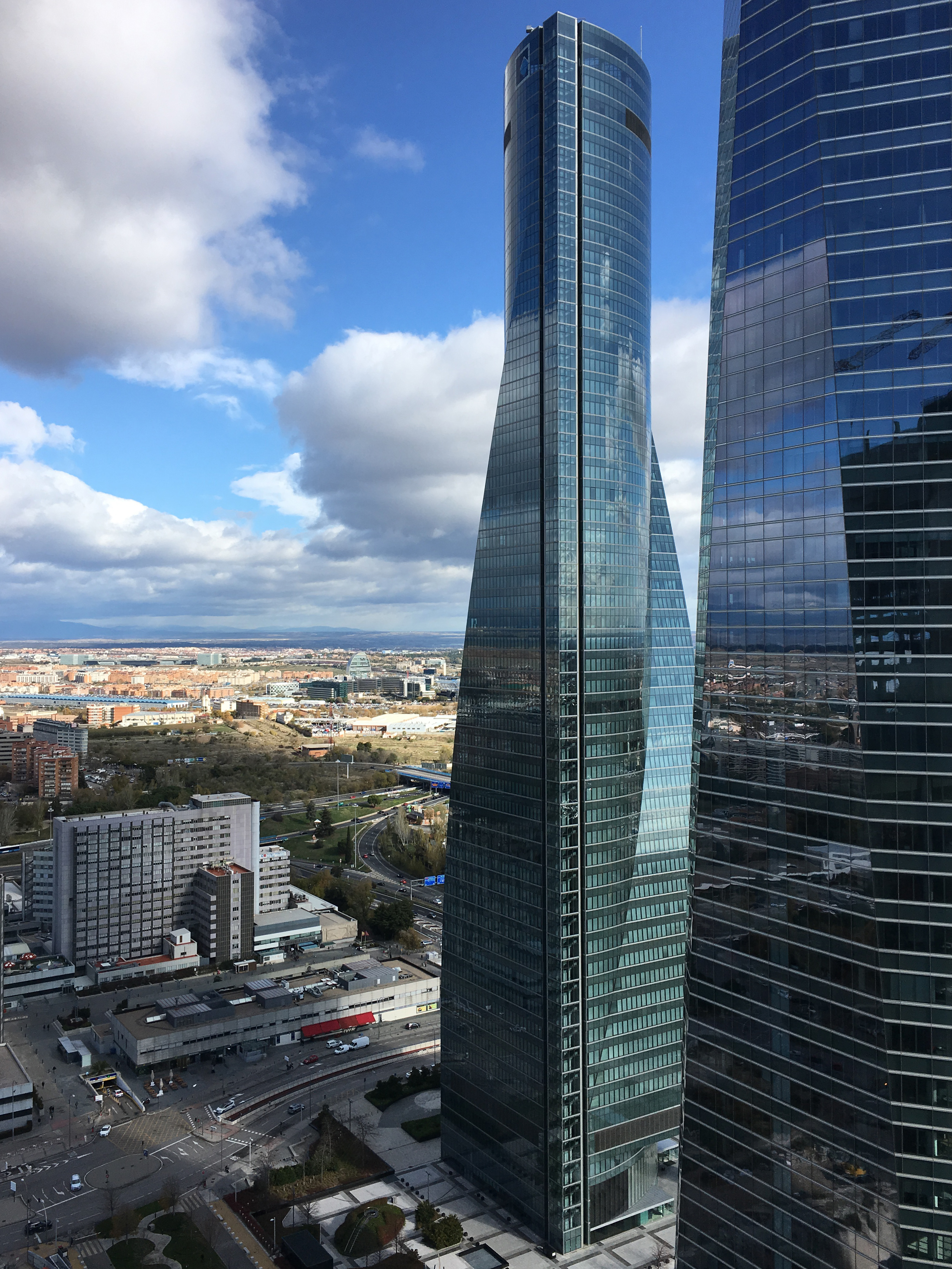
Torre Espacio is the northernmost building. It is 223 m tall and has 56 floors (it´s the smallest of the four buildings). Pei, Cobb Freed & Partners, from New York, was the firm in charge of the architectural design, whilst the structural design was carried out by MC2, from Madrid. The promoter was the Property Company Torre Espacio, owned by the Group Inmobiliaria Espacio.
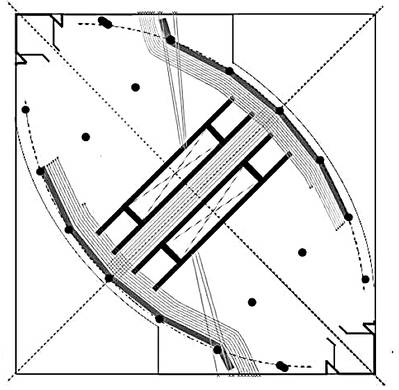
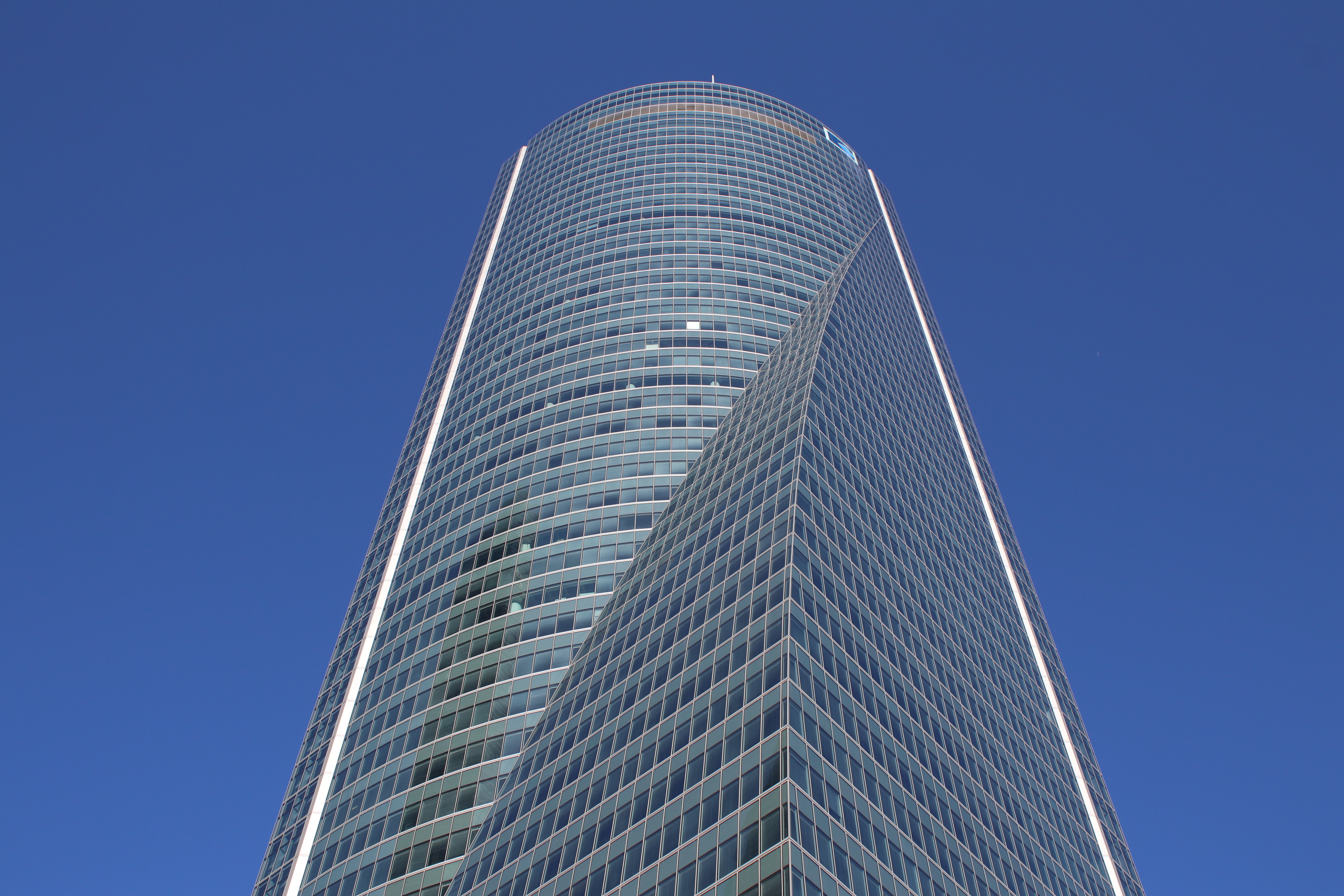
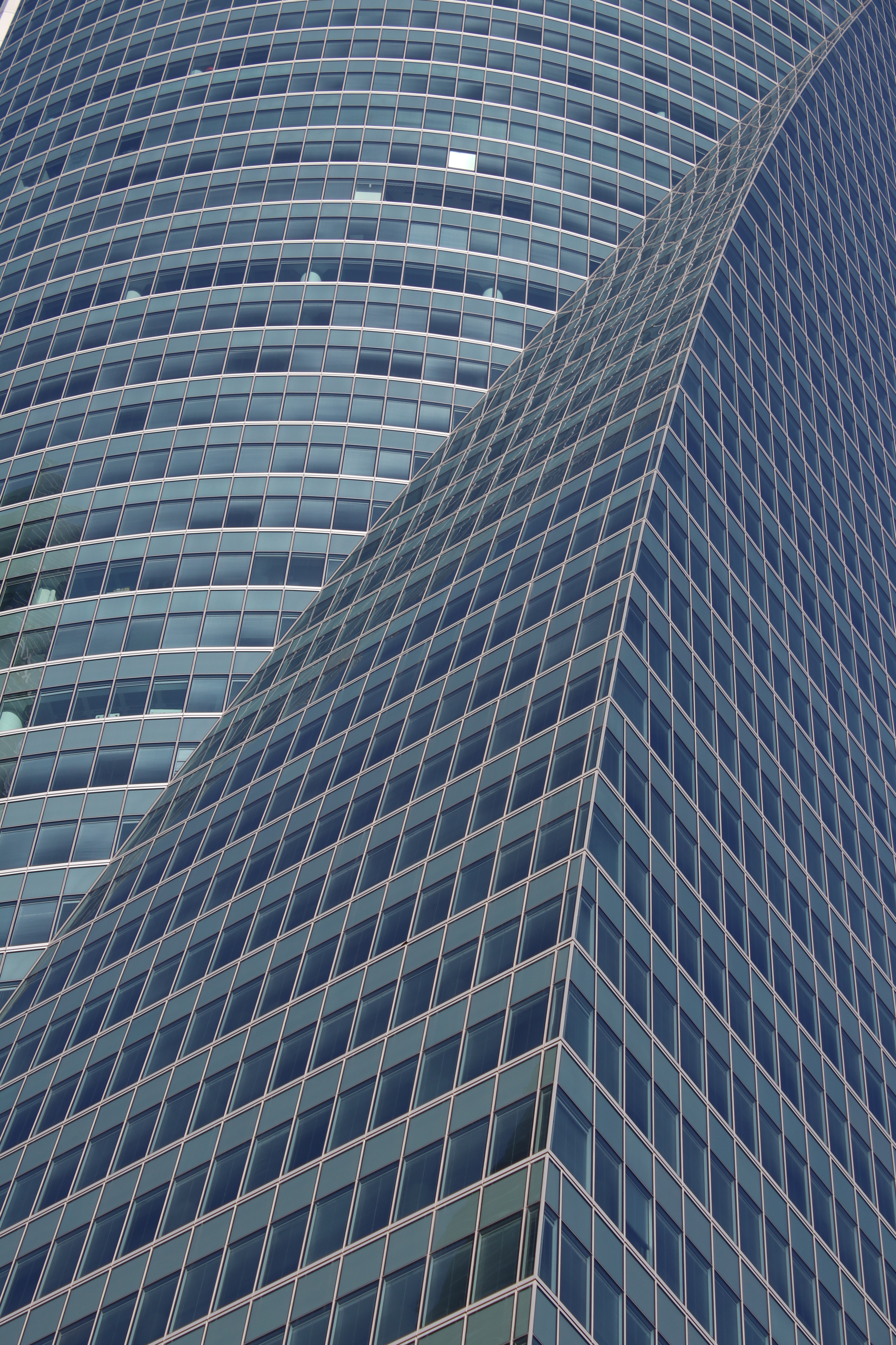
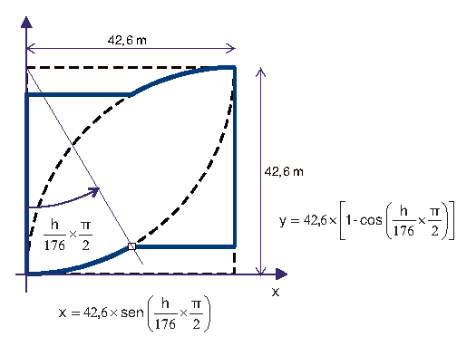
The concept parts from the idea of evolving the building as it rises up. It has a square floor plan at base level of 42 m x 42 m, and it becomes a curved-side diamond at the top, formed by two-quarters of a circle. The objective is to give movement to the tower! The final shape is obtained from a cosine curve. This rationalizes the changes and, because of that, simplifies the construction of the façade elements. However, this makes every floor… different from each other.
Main challenge: wind loads
The design of the structure of a skyscraper has to deal with the lateral loads coming from the wind action and/or seismic action. Madrid is not located in a seismic area, so wind loads will condition the design of the structure.
In order to determine those forces, two wind tunnel tests were carried out. The first one took place at the Higher Technical University of Aeronautical Engineers in Madrid, but results were not precise enough due to limitations when taking into account terrain effects and surrounding buildings (boundary layer). The second one, like the ones which were made for the other towers, were made at the Boundary Layer Wind Tunnel Laboratory at the University Of Western Ontario, Canada. Professor Alan G. Davenport was in charge. They determined the wind loads to be applied for designing the tower. If you want to know more details about wind in these towers, go to the Torre Cepsa project.
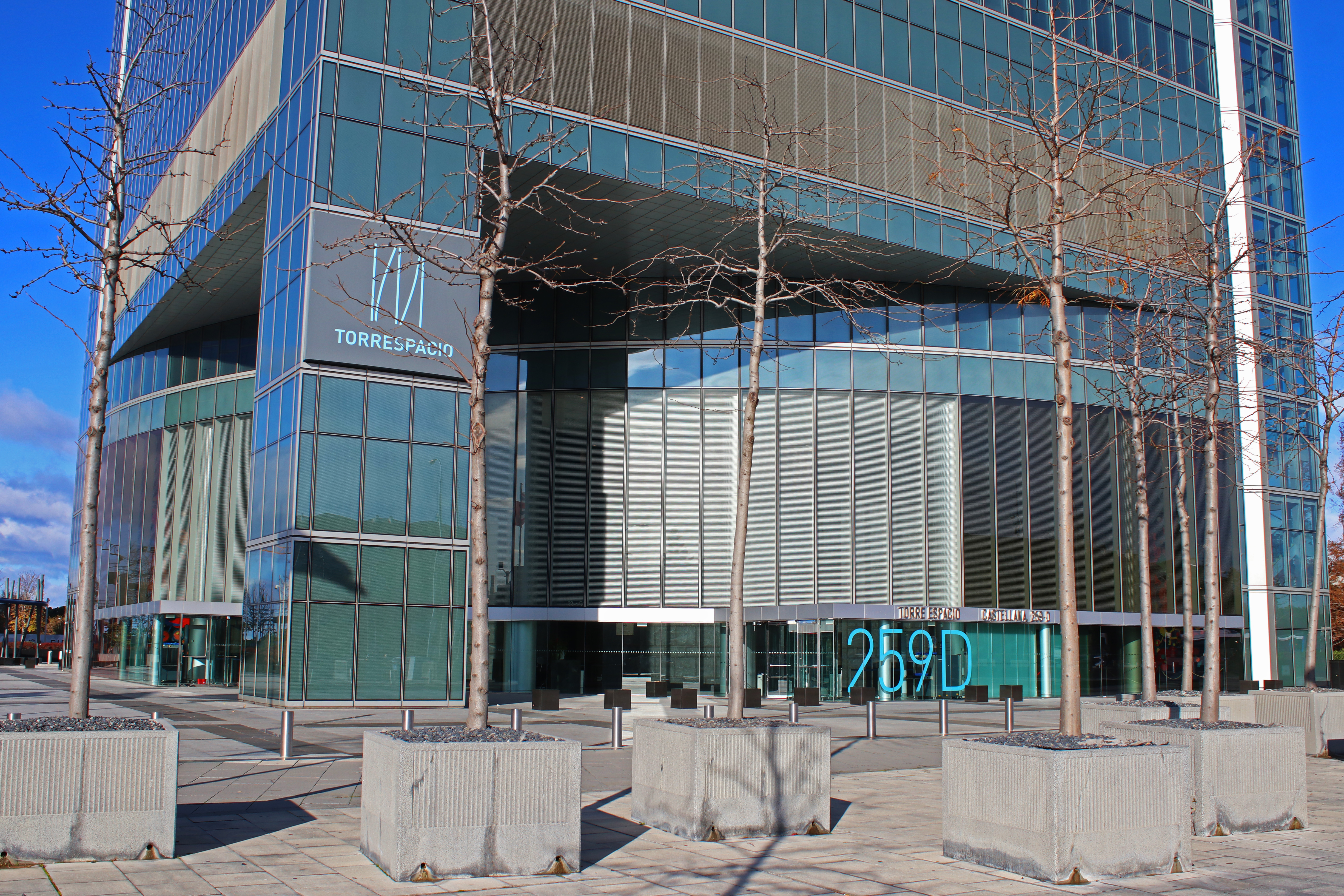
They even studied the effects of wind in the pedestrians walking around the tower, and they concluded that buffer measures were needed to avoid annoying sensations. Those consist of placing trees and urban furniture where needed.
Structural design
Structural design in skyscrapers has to deal with big vertical and lateral loads. In this case, lateral loads come from wind action.
The Torre Espacio structural resistance system against wind loads consists of 3 concrete cores helped by the building columns, which are connected to the cores through the reinforced concrete slab floors.
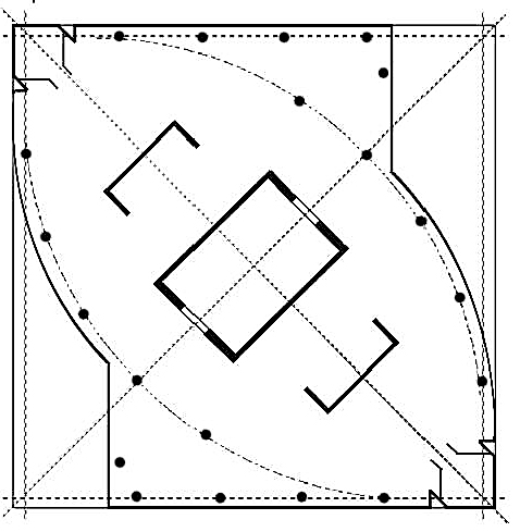
The central core is the biggest and it goes along the whole height of the building. Its hollowed rectangular section has sides of 15 m x 10 m, and the walls are 0,40 to 1,50 m thick. The other two concrete cores are C-shaped with walls 0,30 m thick. At floor 35 they are substituted by concrete columns. Elevators and other services and systems are located inside the cores.
The bigger the surface on which the wind blows, the bigger the total load to be resisted. As the tower is not symmetric, there is an unfavorable direction. The longest side of the central core follows this direction.
There are two groups of columns: the ones in the façade, and the main interior columns. Façade pillars are located in the outside perimeter of the tower, and they mainly contribute to resisting vertical loads and a bit of the lateral loads. Some of them are curved in height, as they follow the façade shape. As floors recede, some of these columns disappear.
The main columns run all along the height of the building, and are the ones resisting a big part of the lateral forces. They are located in the plan of the top diamond perimeter of the building. They are connected to the core through the concrete slabs. To increase lateral rigidity, an outrigger system was designed. It is located between floors 35 and 36, at two-thirds of the height of the tower, where it is most efficient. At that level, the second mechanical floor of the building is located and the side cores and façade columns have already disappeared.
What is this outrigger system? It is a structure formed by reinforced concrete walls one-floor high (4 m) that connect the central core to the main columns, as well as the concrete slab floors. There are two walls along two parallel facades connecting the 5 main columns, plus transversal walls that connect these walls to the core. This is a very effective system against lateral loads. It introduces big axial forces in the columns, thus increasing the rigidity of the whole tower. Walls and slabs at this outrigger system are prestressed elements.
The distribution in the resistance of the wind loads depends on the rigidity of the different elements that have been described. The central core is in charge of resisting about 50% of the total lateral load, whilst main columns take around 20 %. However, the design of these columns is not highly conditioned by wind, as maximum vertical load is not concomitant with the maximum wind load. They are reinforced concrete columns with metallic S355 columns embedded inside. Diameters go up to 1,2 m.
Other interesting structural data
- Why did they choose concrete slabs instead of beam and floor systems? When dealing with complex geometries, as in this case where every floor is different, pouring concrete is much easier and faster than building many different beams. These floors, as it´s been already said, not only contribute to resist vertical loads but also the lateral ones by connecting the central core with the columns.
- Some of the columns are removed below the first mechanical floor, to create a “cleaner” and more open access to the tower. Those column forces have to be transferred. Two big steel trusses (load-bearing beams) are fitted between 1st floor slab and 1st mechanical floor slab. They are 8 m high and span 28 meters to shore the columns from above! Upper and lower cords are connected with the slabs, working as composite sections, and so having a bigger capacity than by themselves. Diagonals are prestressed.
- The foundation of Torre Espacio consists of a 4 meter post-tensioned reinforced concrete slab with a surface bigger than the vertical projection of the tower. Due to the high thickness of this slab, temperatures had to be carefully controlled and limited to certain values during curing process (concrete releases heat when curing and, if temperatures are very high, concrete is damaged).
Materials
Different types of concrete were used:
- HA-30: slab floors.
- HA-80: columns and cores under +23,60 level. The construction company changed from HA-70 to HA-80 to have a safety margin as they were working with a very special concrete pumped higher than 130 m.
- HA-40: columns and cores between +23,60 and +51,60 levels (transition floors).
- HA-30: columns and cores above +51,60 level.
Reinforcing steel: B-500 S.
Structural steel: S 355 J2 G3 in tower supports and load bearing beams.
Prestressing steel Y 1860 S7: foundation slab, load-bearing beams and outrigger elements.
Photos
Pictures


Plans
-

- Central and secondary cores
-
- Central core

-
- Outrigger
-
- Façade design
-
- Façade design


_-_03")


 02b")


